Driven disc assembly punching equipment for automobile clutch machining

A punching equipment and clutch technology, applied in metal processing equipment, drilling/drilling equipment, measuring/indicating equipment, etc., can solve the problems of inconvenient change of punching position, increase the scope of use, affect production efficiency, etc., to achieve Improve equipment adaptability, facilitate debugging, and improve efficiency

Pending Publication Date: 2022-06-03
浙江亿嘉达汽车部件有限公司
View PDF10 Cites 2 Cited by
  • Summary
  • Abstract
  • Description
  • Claims
  • Application Information

AI Technical Summary

Problems solved by technology

[0002] The automobile clutch is located in the flywheel housing between the engine and the gearbox. The clutch assembly is fixed on the rear plane of the flywheel by screws. The output shaft of the clutch is the input shaft of the gearbox, and the driven disc is a component of the automobile clutch. Injection molding is required during the production of the driven disc, and it needs to be punched after the injection molding is completed. In the prior art, the driven disc is generally provided with a plurality of mounting holes around its axis, but the existing Production and processing equipment, when punching the driven disc, the punching position is inconvenient to change, resulting in a decline in overall practicability
[0003] Chinese patent CN202120240648.1 discloses a processing equipment for the production of an automobile clutch driven disc assembly, including a horizontal plate, a support plate, a base, and a guide rod. The lower surface of the horizontal plate is fixed with a support plate, and the bottom end of the support plate The base is fixedly connected, the inside of the horizontal plate is fixedly connected with a guide rod, and the inside of the base is equipped with a transmission mechanism. Used in conjunction with bolts, etc., the rotation of the transmission rod drives the sliding seat to move, and the sliding seat drives the mounting seat to move on the outer wall of the guide rod, and then the mounting seat drives the groove plate and driven plate to move, changing the drilling position and increasing the use range. Seat, groove plate, threaded rod, pressure plate and threaded cap are used in conjunction with each other. Turning the threaded cap on the outer wall of the threaded rod drives the pressure plate to move, and the pressure plate fixes the driven plate. Although the stability of the driven plate’s punching is improved, the Since there are several installation holes on the driven disc, the position needs to be adjusted once each installation hole is drilled, which greatly affects the production efficiency

Method used


Image

  • Driven disc assembly punching equipment for automobile clutch machining
  • Driven disc assembly punching equipment for automobile clutch machining
  • Driven disc assembly punching equipment for automobile clutch machining

Examples


Embodiment Construction

[0038] In order to further understand the features, technical means, and specific goals and functions of the present invention, the present invention will be described in further detail below with reference to the accompanying drawings and specific embodiments.

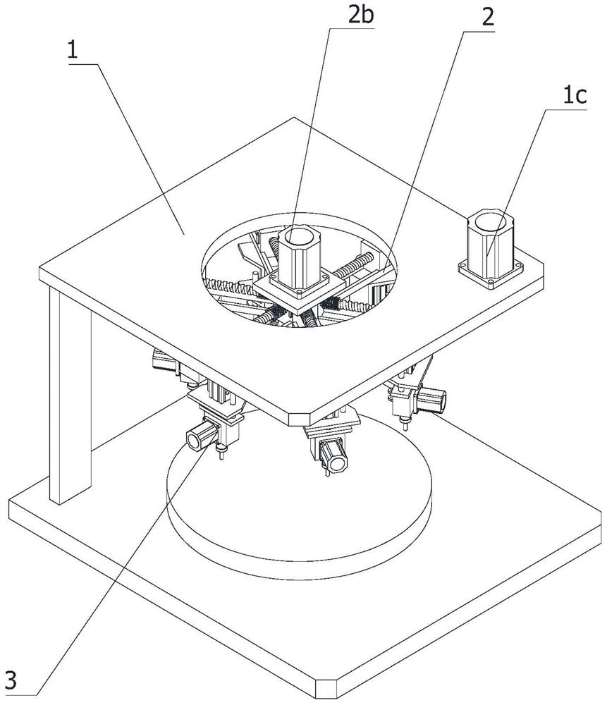
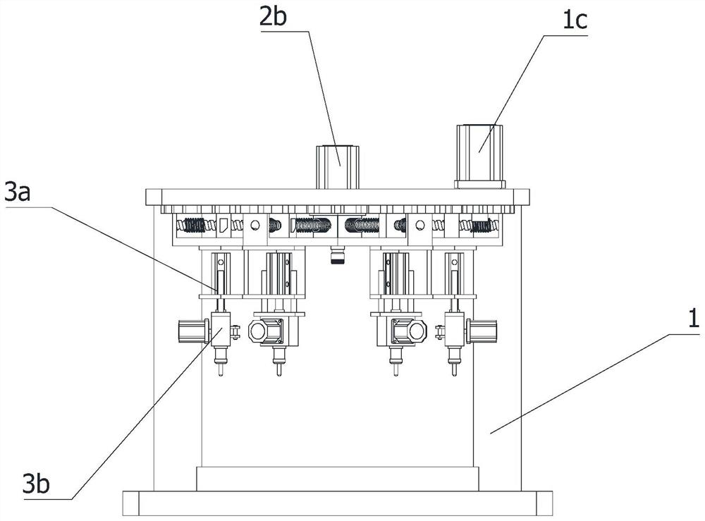
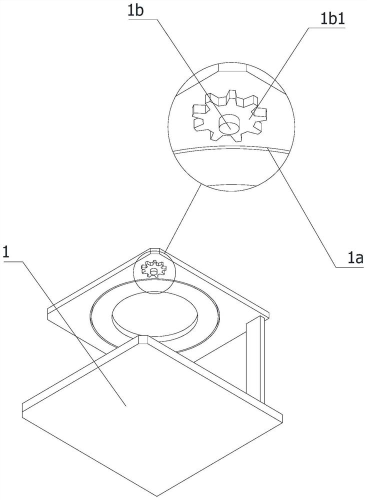
[0039] like Figure 1-10 As shown, this application provides:

[0040]A driven disc assembly punching device for automobile clutch processing, comprising a frame 1, on which a rotating frame 2, a rotating shaft 2a, a first rotating drive motor 2b and several drilling mechanisms 3 are arranged, The rotating frame 2 is a ring-shaped structure, the rotating frame 2 is rotatably located at the top of the frame 1, the rotating shaft 2a is vertically rotatable and is located in the center of the rotating frame 2, and the first rotating drive motor 2b is located on the rotating frame 2. And it is connected with the rotating shaft 2a by transmission. The circumference of the rotating shaft 2a is provided with the extension f...


PUM


Abstract

The invention relates to the technical field of automobile clutches, in particular to driven plate assembly drilling equipment for automobile clutch machining, which comprises a rack, and a rotating frame, a rotating shaft, a first rotating driving motor and a plurality of drilling mechanisms which are arranged on the rack, the drilling mechanism is mounted at the bottom of the rotary shaft, a first rotary driving motor drives the rotary shaft to rotate, a guide groove is formed in each extension frame, a sliding seat and a lead screw are arranged on each guide groove, the lead screws are in threaded fit with the sliding seats, all the lead screws are in transmission connection with the rotary shaft, and the drilling mechanism is mounted at the bottoms of the sliding seats. The rotating shaft drives all the lead screws, the sliding base moves in the direction of the guide groove through the lead screws, so that the drilling mechanism is driven, the drilling mechanism conducts drilling operation on the driven disc, the production efficiency is greatly improved, through the structure, the driven discs with different diameters can be matched by adjusting the position of the sliding base on the guide groove, and the equipment adaptability is improved.

Description

technical field [0001] The invention relates to the technical field of automobile clutches, in particular to a driven plate assembly punching device used for machining automobile clutches. Background technique [0002] The automobile clutch is located in the flywheel housing between the engine and the gearbox. The clutch assembly is fixed on the rear plane of the flywheel by screws. The output shaft of the clutch is the input shaft of the gearbox, and the driven disc is the composition of the automobile clutch. In the production of the driven disc, injection molding is required, and after the injection molding is completed, it needs to be punched. In the prior art, a plurality of mounting holes around the axis of the driven disc are generally provided, but the existing In the production and processing equipment, when punching the driven disc, the punching position is inconvenient to change, which leads to a decrease in the overall practicability. [0003] Chinese patent CN2...

Claims


Application Information

Patent Timeline
Patent Type & Authority Applications(China)
IPC IPC(8): B23B39/20B23B47/26B23B47/20B23Q17/24B23Q17/22B23Q1/25
CPCB23B39/20B23B47/26B23Q5/40B23Q17/2471B23Q17/2233B23Q1/25
Inventor 蒋权士
Owner 浙江亿嘉达汽车部件有限公司
Why Eureka
Try Eureka