
Maintenance device for micro motor

A technology for overhauling devices and micro motors, which is applied to electromechanical devices, manufacturing motor generators, cooling/ventilating devices, etc. Improve the scope of use, good protection, good observation and maintenance effect

Active Publication Date: 2022-05-27
江西昌龙电机有限公司
View PDF7 Cites 0 Cited by
  • Summary
  • Abstract
  • Description
  • Claims
  • Application Information

AI Technical Summary

Problems solved by technology

[0005] The purpose of the present invention is to provide a maintenance device for micro motors, to solve the problem that the existing maintenance devices proposed in the above background technology are usually unable to adjust the device according to the micro motors of different sizes more conveniently when in use. It cannot adapt to various situations well, and at the same time, the staff cannot adjust the device according to their own working habits during use, which has certain limitations and affects the use effect of the device

Method used


Image

  • Maintenance device for micro motor
  • Maintenance device for micro motor
  • Maintenance device for micro motor

Examples


Embodiment 1

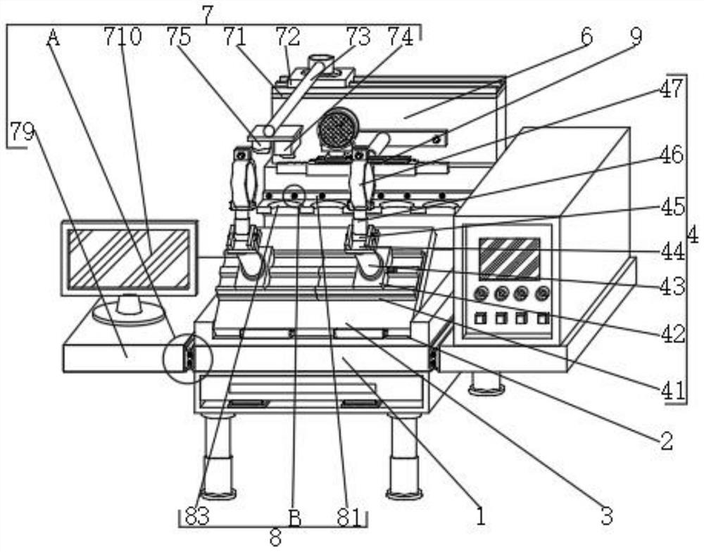
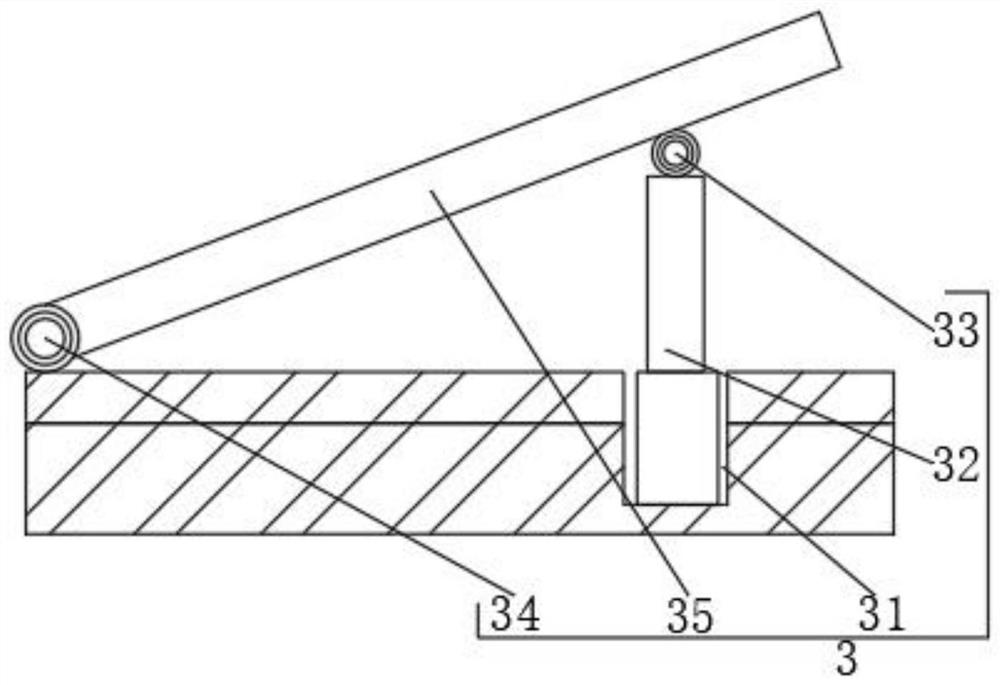
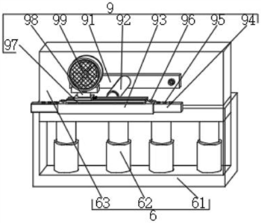
[0032] see Figure 1-6 , In the embodiment of the present invention, an overhaul device for a micro motor includes: an overhaul platform 1 and a mounting slot 2 on the top of the overhaul platform 1, and is characterized in that it also includes an angle adjustment mechanism 3, a shock absorption protection mechanism 5 , the lifting mechanism 6 and the storage mechanism 8, the angle adjustment mechanism 3 is fixedly installed on the top of the installation groove 2, and the shift fixing mechanism 4 is fixedly installed on one side of the angle adjustment mechanism 3; The first connecting plates 41 on both sides of the top of the mechanism 3, the two screw slides 42 fixedly installed on the tops of the two first connecting plates 41, and the two sliding blocks fixedly installed on the tops of the two screw slides 42 respectively The first support rod 43; the shock absorption protection mechanism 5 is fixedly installed on the inner side of the displacement fixing mechanism 4, th...

Embodiment 2

[0034] see figure 1 and Image 6 , and the difference from Embodiment 1 is: a maintenance device for micro-motors, including: the observation mechanism 7 also includes a display 710, two mounting plates 76 fixedly installed on both sides of the two maintenance platforms 1, two There are card slots 77 respectively opened on one side of the two mounting plates 76 , two card blocks 78 fitted on the inner sides of the two card slots 77 , and two support platforms 79 fixed on one side of the two card blocks 78 , respectively. The display 710 is fixedly installed on the top of one of the support platforms 79, and the display 710 can be repaired or replaced more conveniently according to the requirements of use, so as to ensure the best observation of the motor. The observation mechanism 7 includes a second connecting plate 71, an electric sliding The rail 72, the mounting bracket 73, the high-definition camera 74 and the fill light 75, the second connecting plate 71 is fixedly inst...


PUM


Abstract

The invention discloses an overhaul device for a micro motor, which comprises an overhaul stand and a mounting groove formed in the top of the overhaul stand, and also comprises an angle adjusting mechanism, a damping protection mechanism, a lifting mechanism and a storage mechanism, and is characterized in that the angle adjusting mechanism is fixedly mounted at the top of the mounting groove; and a displacement fixing mechanism is fixedly mounted on one side of the angle adjusting mechanism. According to the device, by arranging the angle adjusting mechanism, the displacement fixing mechanism and the damping protection mechanism, an electric push rod is opened to enable the telescopic end of the electric push rod to drive one side of the operation table to move upwards, the operation table drives a hinge on one side to rotate in the moving process, and a first pin shaft at the telescopic end of the electric push rod is also matched with the operation table to rotate and move; and when the operation table rotates to the appropriate position and angle of the moving channel, the electric push rod is closed, the angle of the operation table can be adjusted more conveniently according to the use requirements of different workers, and the workers can adopt the best posture when using the device.

Description

technical field [0001] The invention relates to the field of micro-motor equipment, in particular to a maintenance device for micro-motors. Background technique [0002] A micro motor is a type of motor with a small volume and a small capacity, and the output power is generally below several hundred watts. A special type of motor, micro motor is a high-tech industry that integrates motors, microelectronics, power electronics, computers, automatic control, precision machinery, new materials and other disciplines, especially the application of electric, microelectronics and new material technologies It has promoted the technological progress of micro and special motors. There are many varieties of micro motors, various specifications, and a wide range of market applications, involving all aspects of the national economy, national defense equipment, and human life. Micro motors and micro motors can be seen wherever electric drive is required. In the process of production and u...

Claims


Application Information

Patent Timeline
Patent Type & Authority Applications(China)
IPC IPC(8): H02K15/00H02K5/26H02K5/24H02K9/04
CPCH02K15/0006H02K5/26H02K5/24H02K9/04Y02E10/72
Inventor 伍银龙伍年喜黄纪滨
Owner 江西昌龙电机有限公司
Learn More