
Air cooler

An air cooler and cooling structure technology, applied in cooling/ventilation devices, electrical components, electromechanical devices, etc., can solve the problems of large air circulation resistance, affecting the operation effect of the motor cooling system, etc., to ensure the cooling effect, compact structure, The effect of high work efficiency

Pending Publication Date: 2022-05-27
STATE GRID CORP OF CHINA +3
View PDF0 Cites 0 Cited by
  • Summary
  • Abstract
  • Description
  • Claims
  • Application Information

AI Technical Summary

Problems solved by technology

[0005] Therefore, the technical problem to be solved by the present invention is to overcome the air circulation resistance in the air cooler which affects the operation of the motor cooling system when the air cooler with cooling fan in the prior art drives the air flow components in the motor to work normally. effect, so as to provide an air cooler that always maintains a good cooling effect in the working state

Method used


Image

  • Air cooler
  • Air cooler
  • Air cooler

Examples


Embodiment Construction

[0030] The technical solutions of the present invention will be clearly and completely described below with reference to the accompanying drawings. Obviously, the described embodiments are a part of the embodiments of the present invention, but not all of the embodiments. Based on the embodiments of the present invention, all other embodiments obtained by those of ordinary skill in the art without creative efforts shall fall within the protection scope of the present invention.

[0031] In addition, the technical features involved in the different embodiments of the present invention described below can be combined with each other as long as they do not conflict with each other.

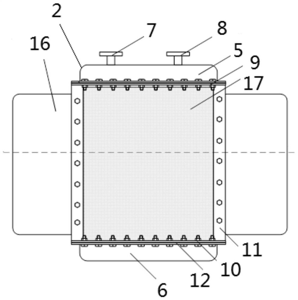
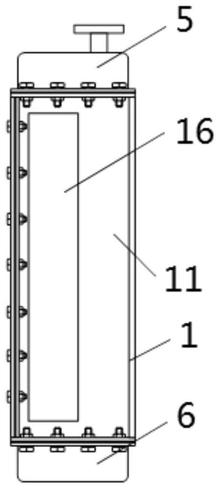
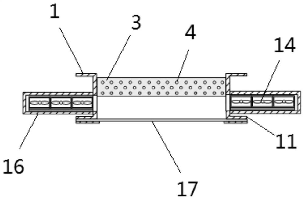
[0032] like Figures 1 to 6 A specific embodiment of the shown air cooler, the air cooler is installed and fixed on the back of the vertical hydro-generator or generator motor through the back plate 1, which can be realized by welding or fastening standard parts. The reliable connection of the two i...


PUM


Abstract

The invention relates to the technical field of cooling devices, in particular to an air cooler which comprises a shell internally provided with a cooling structure. The air blowing structure is movably arranged on the shell and has a first state that the air blowing structure moves to the side part of the cooling structure when a driving structure corresponding to the air cooler works normally so as to expose at least part of the cooling structure; and in the second state, when the driving structure corresponding to the air cooler stops working, at least part of the cooling structure is covered, so that air is introduced into the cooling structure. The invention provides the air cooler which always keeps a good cooling effect in a working state.

Description

technical field [0001] The invention relates to the technical field of cooling and cooling devices, in particular to an air cooler. Background technique [0002] The hydro-generator and generator-motor will generate a lot of heat during operation. Generally, the heat will be transferred to the air inside the motor through a specific structure, and the heat will be taken out of the motor through the circulating flow of air inside and outside the motor. After the heat in the air is transferred to the secondary cooling medium, the air temperature drops, enters the motor again to absorb heat, and circulates in turn, thereby realizing the cooling of the hydro-generator and the generator-motor. There are generally several air coolers for vertical hydro-generators and generator-motors, which are symmetrically distributed on the back of the stator iron core for secondary cooling of the hot air in the motor ventilation system. There is a cold water pipeline in the water-cooled air c...

Claims


Application Information

Patent Timeline
IPC IPC(8): H02K9/04H02K9/19H02K5/18H02K5/10
CPCH02K9/04H02K9/19H02K5/18H02K5/10Y02E10/20
Inventor 狄洪伟张政陈金秀杨斌莫亚波陆婷李赟俐陈裕文胡坤王开成姚航宇
Owner STATE GRID CORP OF CHINA
Learn More