
Obstacle detection processing method, device, equipment and system based on binocular camera

A binocular camera and processing device technology, applied in the field of sensor processing, can solve problems such as loss of some points, limited detection distance, poor depth information accuracy of binocular cameras, etc., to achieve improved effectiveness, integrity assurance, and long perception distance Effect

Pending Publication Date: 2022-05-24
GUANGDONG HUITIAN AEROSPACE TECH CO LTD
View PDF0 Cites 2 Cited by
  • Summary
  • Abstract
  • Description
  • Claims
  • Application Information

AI Technical Summary

Problems solved by technology

[0003] In related technologies, both the binocular camera and the lidar can obtain the three-dimensional information of obstacles, but the accuracy of the depth information of the binocular camera is poor, and when the lidar detects large obstacles in the middle and long distances, the point cloud is not dense enough or partially Point loss and other situations, resulting in limited detection distance
[0004] Therefore, the data obtained by the laser radar and the binocular camera in the related art are insufficient, especially when encountering a large obstacle, it is difficult to detect the outline of the obstacle, and it is impossible to obtain accurate information about the large obstacle, thereby reducing the Effectiveness of path planning

Method used


Image

  • Obstacle detection processing method, device, equipment and system based on binocular camera
  • Obstacle detection processing method, device, equipment and system based on binocular camera
  • Obstacle detection processing method, device, equipment and system based on binocular camera

Examples


Embodiment Construction

[0051] The present application will be described in more detail below with reference to the drawings. Although the accompanying drawings show embodiments of the present application, it should be understood that the present application may be implemented in various forms and should not be limited by the embodiments described herein. Instead, these embodiments are provided in order to make the present application more thorough and complete, and to be able to communicate the scope of the present application completely to those skilled in the art.

[0052] The terms used in this application are for the purpose of describing a particular embodiment only, and are not intended to limit the present application. The singular forms used in this application and the appended claims are also intended to include most forms, unless the context clearly indicates other meanings. It should also be understood that the term "and / or" as used herein refers to and comprises any or all possible combina...


PUM


Abstract

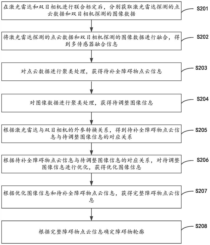
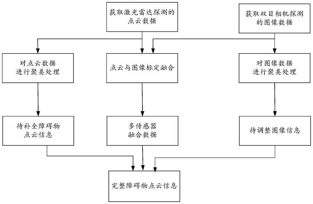
The invention relates to an obstacle detection processing method, device and system based on a binocular camera. The method comprises the following steps: acquiring point cloud data detected by a radar and image data detected by a binocular camera; performing clustering processing on the point cloud data and the image data to obtain to-be-completed obstacle point cloud information and to-be-adjusted image information corresponding to an obstacle; optimizing the to-be-adjusted image information according to a corresponding relation between the to-be-complemented obstacle point cloud information and the to-be-adjusted image information to obtain optimized image information; obtaining complete obstacle point cloud information according to the optimized image information and the to-be-completed obstacle point cloud information; and determining the contour of the obstacle according to the complete obstacle point cloud information. According to the scheme provided by the invention, the contour of the large obstacle can be detected more accurately, and the effectiveness of path planning is improved.

Description

Technical field [0001] The present application relates to the field of sensor processing technology, in particular to a binocular camera-based obstacle detection processing method, apparatus, apparatus and system. Background [0002] In order to improve driving safety and facilitate route planning, sensors are used to detect obstacles in areas such as aircraft or automobiles. At present, binocular cameras and lidar can be used for roadblock detection. [0003] In related technologies, binocular cameras and lidar can obtain three-dimensional information of obstacles, but the depth information accuracy of binocular cameras is poor, and lidar will have a point cloud that is not dense enough or some points are missing when detecting large obstacles at medium and long distances, resulting in a limited detection distance. [0004] Therefore, the data obtained by lidar and binocular cameras in related technologies to detect obstacles are insufficient, especially when encountering large ...

Claims


Application Information

Patent Timeline
Patent Type & Authority Applications(China)
IPC IPC(8): G06V20/58G06V10/762G06V10/80G06V10/44G06K9/62
CPCG06F18/23213G06F18/251
Inventor 赵德力郭均浩谷靖张新
Owner GUANGDONG HUITIAN AEROSPACE TECH CO LTD
Learn More