
Electricity generation power device rotating mechanism and beam transporting vehicle

A technology of power devices and rotating mechanisms, which is applied in the direction of electric power devices, power devices, motor vehicles, etc., can solve problems such as easy to pull cables, loose cables, and affect the power transmission of the front vehicle, so as to achieve good applicability, convenient movement, and avoid The effect of restricted turning

Active Publication Date: 2022-05-13
CHINA TIESIJU CIVIL ENG GRP CO LTD
View PDF7 Cites 0 Cited by
  • Summary
  • Abstract
  • Description
  • Claims
  • Application Information

AI Technical Summary

Problems solved by technology

[0003] However, the work of laying cables is relatively cumbersome, and when the movement of the front car and the rear car of the split beam transport vehicle are inconsistent (such as when turning), it is easy to pull the cable, resulting in loosening of the cable and affecting the power transmission of the front car

Method used


Image

  • Electricity generation power device rotating mechanism and beam transporting vehicle
  • Electricity generation power device rotating mechanism and beam transporting vehicle
  • Electricity generation power device rotating mechanism and beam transporting vehicle

Examples


Embodiment Construction

[0024] In order to make the above objects, features and advantages of the present invention more comprehensible, specific embodiments of the present invention will be described in detail below in conjunction with the accompanying drawings.

[0025] It should be noted that in the coordinate system XYZ provided in this article, the positive direction of the X-axis represents the right, the reverse direction of the X-axis represents the left, the positive direction of the Y-axis represents the rear, the reverse direction of the Y-axis represents the front, and the reverse direction of the Z-axis represents the front. The positive direction represents the upward direction, and the reverse direction of the Z axis represents the downward direction. At the same time, it should be noted that the terms "first" and "second" in the description and claims of the present invention and the above drawings are used to distinguish similar objects, and not necessarily used to describe a specific...


PUM


Abstract

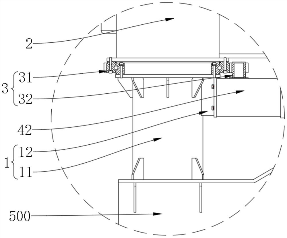
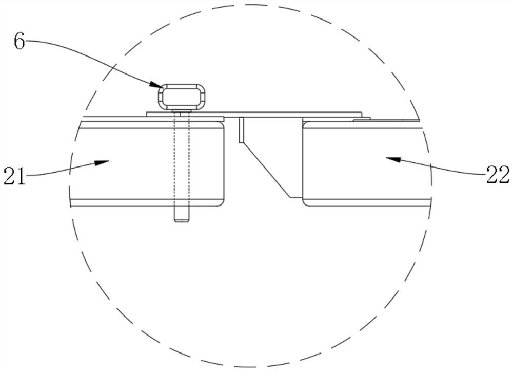
The invention provides a power generation power device rotating mechanism and a girder transporting vehicle, the power generation power device rotating mechanism comprises a rotating support, a mounting bracket, a rotating assembly and a driving assembly, the mounting bracket is used for mounting a power generation power device of a front vehicle of the girder transporting vehicle, one end of the rotating support is suitable for being connected to a front vehicle body of the girder transporting vehicle, and the other end of the rotating support is suitable for being connected to a rear vehicle body of the girder transporting vehicle; the other end of the rotating support is rotationally connected with the mounting support through the rotating assembly, and the driving assembly drives the rotating assembly to drive the mounting support to rotate so that the power generation power device can be screwed into or screwed out of the containing channel of the beam piece. The electricity generation power device rotating mechanism can be arranged on the front vehicle body of the beam transporting vehicle, so that the power of the front vehicle is conveyed from the rear vehicle without depending on a cable, and the work of laying the cable is omitted; meanwhile, the power generation power device can rotate relative to the front vehicle body, a containing channel of the beam piece is reserved, or the rotating assembly is driven to rotate reversely to move the power generation power device to the front vehicle body, so that the split type beam transporting vehicle can move and pass through a tunnel conveniently.

Description

technical field [0001] The invention relates to the technical field of engineering machinery, in particular to a rotating mechanism of a generating power unit and a beam transport vehicle. Background technique [0002] The beam transport vehicle is a machine designed to transport beams for the erection of highway and railway bridges. The power generation device of the beam transport vehicle mainly includes components or components such as generators and distribution boxes. At present, the power generation power unit of the beam transport vehicle is usually concentrated and fixed at the rear of the vehicle body, but for the split beam transport vehicle, the power generation power unit is usually fixed on the rear vehicle, and the power generation power unit is used as the power assembly of the whole vehicle for the transport. The front car and the rear car of the beam car provide power, so the front car usually needs to be powered by the rear car through cables. [0003] How...

Claims


Application Information

Patent Timeline
Patent Type & Authority Applications(China)
IPC IPC(8): B60K1/00B60P3/00
CPCB60K1/00B60P3/00
Inventor 管新权陈志远伍莲桥段启楠吴辰龙王道成陈浩王薇黄凯
Owner CHINA TIESIJU CIVIL ENG GRP CO LTD
Learn More