
Intelligent vision detection system

A vision detection and intelligent technology, applied in eye testing equipment, various biometric identification applications, instruments, etc., can solve problems such as low detection efficiency, errors in historical user information, and unreliable sources of historical user information.

Active Publication Date: 2022-05-13
GUANGZHOU VISION OPTICS TECH
View PDF7 Cites 1 Cited by
  • Summary
  • Abstract
  • Description
  • Claims
  • Application Information

AI Technical Summary

Problems solved by technology

[0002] At present, the traditional visual acuity testing process needs to be completed manually and accompanied by professionals, and the traditional visual acuity testing box is provided with overall lighting, which cannot provide targeted lighting for the test standard characters during visual acuity testing , it is necessary to manually instruct the testee to test the corresponding test standard words, and the test process is mainly through the instructions of the professional and the language communication between the professional and the testee, so as to realize the test process, the dependence on the professional is changed, and it is easy to appear error, and the detection efficiency is not high;
[0003] Moreover, the traditional vision detection process needs to verbally inquire or retrieve historical user information in the computer to obtain the user's historical user information, and then designate a detection plan, which leads to inefficiency and insufficient source of historical user information Reliable, which may lead to errors in historical user information, resulting in errors in the detection plan, which in turn leads to inaccurate detection results;

Method used


Image

  • Intelligent vision detection system
  • Intelligent vision detection system
  • Intelligent vision detection system

Examples


Embodiment 1

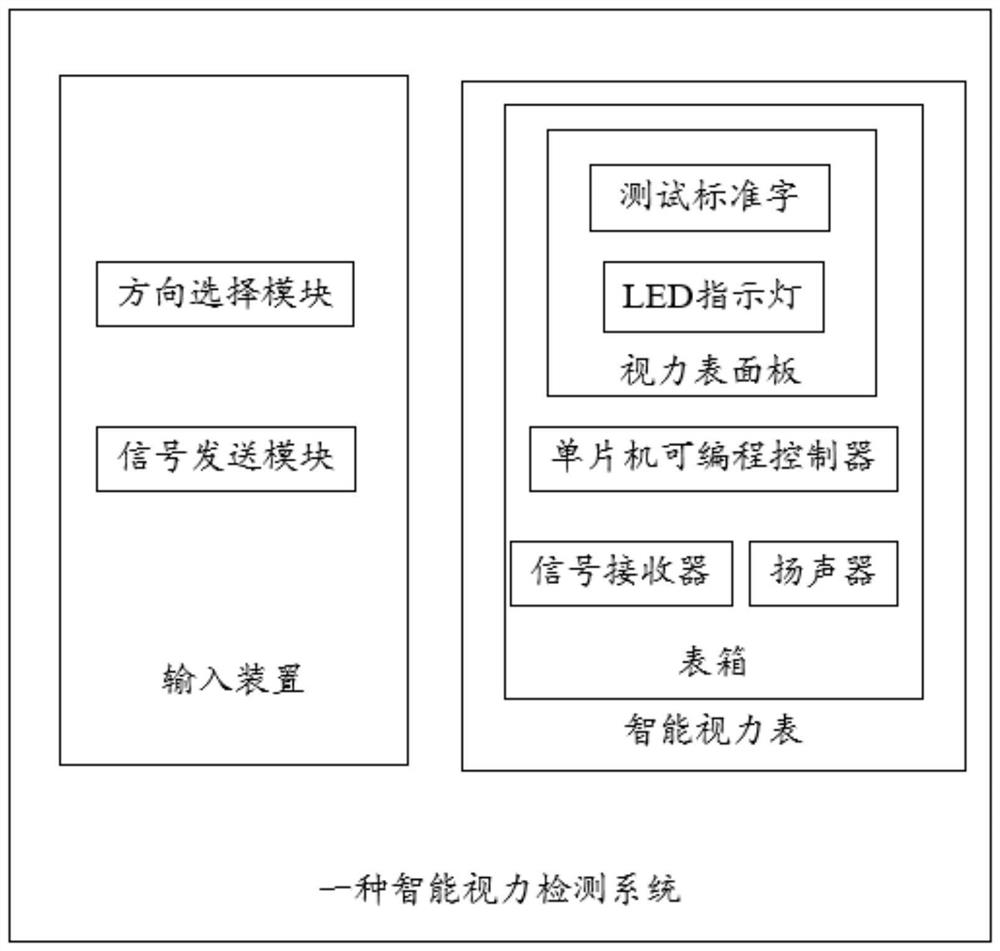
[0070] The present invention proposes an intelligent vision detection system, referring to figure 1 , including: an intelligent vision chart and an input device; the intelligent vision chart includes a watch box, and a vision surface panel is arranged on the said watch box; a test standard word is arranged on the vision surface panel, and There are LED indicator lights, and the position and quantity of the LED indicator lights are all in one-to-one correspondence with the test standard words on the visual acuity surface board; a single-chip programmable controller, a signal receiver and a loudspeaker are also arranged in the said meter box; The LED indicator light, the signal receiver and the loudspeaker are all connected to the single-chip programmable controller through a signal line; a direction selection module and a signal sending module are arranged in the input device.

[0071] The beneficial effects of the above technology are: the present invention is provided with te...

Embodiment 2

[0073] On the basis of embodiment 1, described a kind of intelligent eyesight detection system comprises:

[0074] The single-chip programmable controller is used to generate a light-emitting control signal corresponding to each LED indicator light;

[0075] The LED indicator light is used for emitting light based on a corresponding light emitting control signal.

[0076] In this embodiment, the light emission control signal is a signal for controlling the light emission of the corresponding LED indicator light.

[0077] The beneficial effects of the above technologies are: the single-chip programmable controller generates the corresponding light-emitting control signal of each LED indicator light, and then controls the corresponding LED indicator light to emit light, and can complete the test process without manual instruction or language communication, reducing the need for communication. The dependence of professionals reduces the error of vision detection and improves the...

Embodiment 3

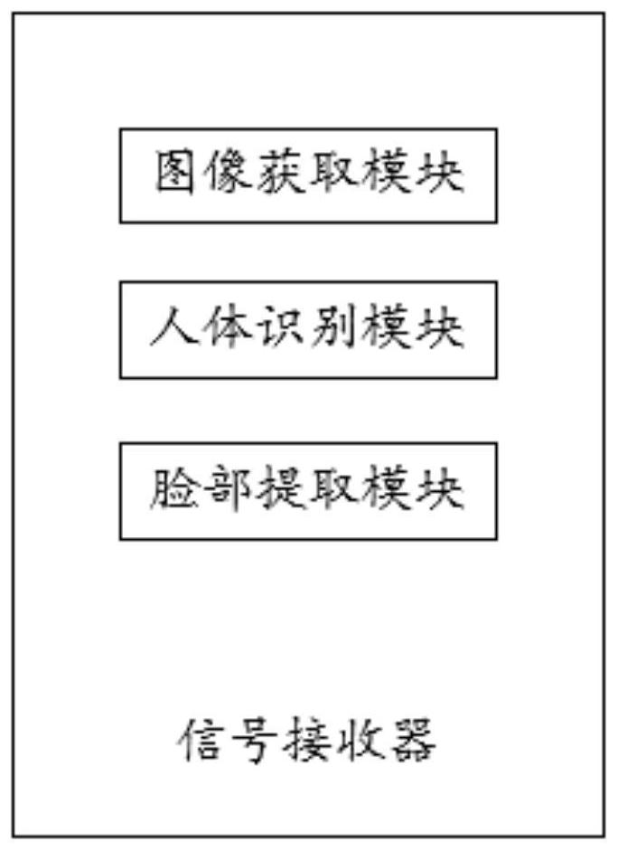
[0079] On the basis of Embodiment 1, the signal receiver refers to figure 2 ,include:

[0080] An image acquisition module, configured to acquire scene images within a preset range directly in front of the vision surface panel in real time;

[0081] A human body recognition module, used for real-time identification of whether there is a human body image in the newly acquired first scene image;

[0082] A face extraction module, configured to identify a corresponding face image from the human body image when the human body image exists in the first scene image.

[0083] In this embodiment, the scene image is an image including a scene within a preset range directly in front of the vision surface board.

[0084] In this embodiment, the preset range may be manually set.

[0085] In this embodiment, the first scene image is the newly acquired scene image within a preset range directly in front of the vision surface board.

[0086] In this embodiment, the human body image is a...


PUM


Abstract

The invention provides an intelligent vision detection system. The intelligent vision detection system comprises an intelligent visual chart and an input device, the intelligent visual chart comprises a chart box, and a visual chart panel is arranged on the chart box. The visual chart panel is provided with test standard characters, the rear part of the visual chart panel is provided with LED indicating lamps, and the positions and the number of the LED indicating lamps are in one-to-one correspondence with those of the test standard characters on the visual chart panel; the meter box is also internally provided with a single-chip microcomputer programmable controller, a signal receiver and a loudspeaker. The LED indicating lamp, the signal receiver and the loudspeaker are all connected with the single-chip microcomputer programmable controller through signal lines. A direction selection module and a signal sending module are arranged in the input device; the method and the device are used for realizing intelligent operation of vision detection and improving the accuracy and efficiency of vision detection.

Description

technical field [0001] The invention relates to the technical field of vision detection, in particular to an intelligent vision detection system. Background technique [0002] At present, the traditional visual acuity testing process needs to be completed manually and accompanied by professionals, and the traditional visual acuity testing box is provided with overall lighting, which cannot provide targeted lighting for the test standard characters during visual acuity testing , it is necessary to manually instruct the testee to test the corresponding test standard words, and the test process is mainly through the instructions of the professional and the language communication between the professional and the testee, so as to realize the test process, the dependence on the professional is changed, and it is easy to appear error, and the detection efficiency is not high; [0003] Moreover, the traditional vision detection process needs to verbally inquire or retrieve historic...

Claims


Application Information

Patent Timeline
Patent Type & Authority Applications(China)
IPC IPC(8): A61B3/032G06V40/70G06V10/74G06K9/62
CPCA61B3/032A61B3/0008A61B3/0033A61B3/0041G06F18/22Y02B20/40
Inventor 伍卫东
Owner GUANGZHOU VISION OPTICS TECH
Learn More