
Power lift for a wind turbine

A wind turbine and power technology, applied in the control of wind turbines, wind turbines, motors, etc., can solve the problems of increasing the cumulative structural damage of wind turbine components, and achieve the effect of increasing AEP

Pending Publication Date: 2022-04-26
SIEMENS GAMESA RENEWABLE ENERGY AS
View PDF0 Cites 0 Cited by
  • Summary
  • Abstract
  • Description
  • Claims
  • Application Information

AI Technical Summary

Problems solved by technology

This extra pitch travel is not necessary and due to high loads it can greatly increase the cumulative structural damage in wind turbine components such as pitch bearings

Method used


Image

  • Power lift for a wind turbine
  • Power lift for a wind turbine
  • Power lift for a wind turbine

Examples


Embodiment Construction

[0028] The description in the drawings is schematic. Note that in different diagrams, the same drawing markers are provided to similar or identical features.

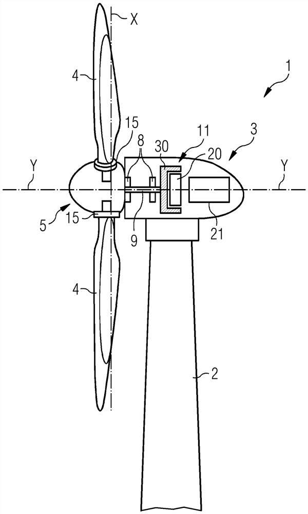
[0029] Figure 1 Illustrated according to the present invention of a wind turbine 1. Wind turbine 1 includes a tower mounted on an undescribed base 2. Cabin 3 is arranged on top of Tower 2. Wind turbine 1 further includes a wind rotor having at least one blade 4 (in Figure 1 In an embodiment, the wind rotor comprises three blades 4, wherein only two blades 4 are visible). Wind rotor 5 rotates around the hinge axis Y. Blade 4 is substantially radial with respect to the hinge Y and extends along the corresponding longitudinal axis X.

[0030] Wind turbine 1 includes a generator 11, the generator 11 includes a stator 20 and a rotor 30. Rotor 30 with respect to the stator 20 may be rotated around the hinge Y. Wind rotor 5 direct (e.g. direct drive) or with the help of a rotatable spindle 9 and / or via a gearbox ( Figure 1 N...


PUM


Abstract

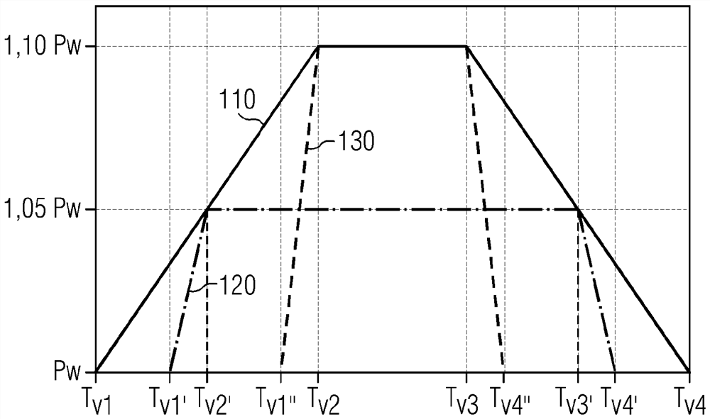
A method of controlling a wind turbine (1) comprises the step of boosting an output power of the wind turbine above a nominal power (Pw) of the wind turbine according to a boost operating function (110, 120, 130) representative of a boost level of the wind turbine (1). The boost operating function (110, 120, 130) is a progressive function of the operating variable at least between a first threshold value (Tv1, Tv1 ', Tv1' ') and a second threshold value (Tv2, Tv2') of the operating variable.

Description

Technical field [0001] The present invention relates to a control of a wind turbine for power increase or increase the nominal power of a wind turbine above the nominal power of a wind turbine. [0002] Technical background [0003] Wind turbines can provide a power boost, i.e., there is a possibility of increasing the power beyond the nominal power value. The speed increases with the power. The boost is configurable and can be set to 5% of the nominal power by default. If generator and converter capacity allows this, the power boost can be increased to a higher amount, such as 10% of the nominal power. This overcapacity can be used, for example, to increase power in strong winds. [0004] According to possible known embodiments, when the pitch angle (pitch angle) and wind speed reach above a predetermined threshold, the power increase in power generation is gradually increased. This is done to ensure that, in the case of most extreme load drive components designs, the power is n...

Claims


Application Information

Patent Timeline
Patent Type & Authority Applications(China)
IPC IPC(8): F03D7/04
CPCF03D7/028F03D7/0224F05B2270/335F05B2270/1033F05B2270/32F05B2270/328Y02E10/72
Inventor J·G·W·阿尔伯茨B·S·卡莱索
Owner SIEMENS GAMESA RENEWABLE ENERGY AS
Learn More