
Shell-and-tube heat exchanger

A technology of shell-and-tube heat exchangers and shells, which is applied to the types of heat exchangers, shells of heat exchangers, indirect heat exchangers, etc., which can solve the time-consuming and laborious disassembly and assembly of heat exchangers and high maintenance costs of heat exchangers , low reliability of heat exchanger seals, etc., to achieve the effect of small quantity, easy disassembly and assembly, and reduced maintenance costs

Pending Publication Date: 2022-04-26
济南新材料产业技术研究院
View PDF6 Cites 0 Cited by
  • Summary
  • Abstract
  • Description
  • Claims
  • Application Information

AI Technical Summary

Problems solved by technology

[0008] The purpose of the present invention is to overcome the deficiencies of the prior art and provide a shell-and-tube heat exchanger, which solves the problem of low sealing reliability of the heat exchanger and solves the time-consuming and laborious problem of disassembling and assembling the existing heat exchanger. , which solves the problem of high manufacturing and maintenance costs of existing heat exchangers

Method used


Image

  • Shell-and-tube heat exchanger
  • Shell-and-tube heat exchanger
  • Shell-and-tube heat exchanger

Examples


Embodiment 1

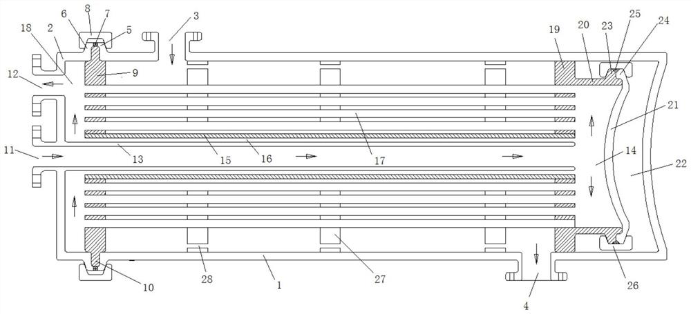
[0033] This embodiment provides a shell and tube heat exchanger, such as figure 1 As shown, it includes a shell 1 with one end open. The shell 1 is a cylindrical shell or a cubic shell. The shell 1 in this embodiment is a cylindrical shell.

[0034] The open end of the housing is provided with an end cover 2, and the end cover 2 and the housing 1 jointly form a closed heat exchange space.

[0035] The shell wall of the housing 1 is provided with a shell-side fluid inlet 3 and a shell-side fluid outlet 4. In this embodiment, the shell-side fluid inlet 3 is set at the end of the shell 1 close to the end cover 2, and the shell-side fluid outlet 4 is set at The other end of the shell 1, and the shell-side fluid inlet 3 is set on the top of the shell 1, and the shell-side fluid outlet 4 is set on the bottom of the shell 1. With this arrangement, it is convenient for the shell-side fluid to flow within the entire shell 1. The flow makes the heat exchange more sufficient.

[0036] ...


PUM


Abstract

The shell-and-tube heat exchanger comprises a shell, the open end of the shell is connected with an end cover, a fixed plate is arranged in the shell, a protruding structure is arranged at the connecting position of the shell and the end cover and comprises a first flange arranged on the shell and a second flange arranged on the end cover, and a sealing ring is arranged between the first flange and the second flange. Positioning grooves are formed in the inner side faces of the first flange, the second flange and the sealing ring, positioning rings inserted into the inserting grooves are arranged on the periphery of the fixed plate, clamping grooves are formed in the inner side faces of the clamping pieces, and the clamping pieces are clamped and fixed to the protruding structures through the clamping grooves. When the heat exchanger is maintained, disassembly and assembly are convenient, time and labor are saved, and the sealing reliability is good.

Description

technical field [0001] The invention relates to the technical field of heat exchangers, in particular to a shell-and-tube heat exchanger. Background technique [0002] The statements herein merely provide background information related to the present invention and do not necessarily constitute prior art. [0003] Heat exchangers are widely used in various production processes. There are many types of heat exchangers, among which the shell-and-tube heat exchanger has a simple and reliable structure and is the most widely used. [0004] Existing shell-and-tube heat exchangers include components such as heat dissipation tube groups, fixed plates, moving plates, tube boxes, end covers, flanges, gaskets, interfaces, and accessories. Connection bolts need to be set at the joints between the end cover and the shell. Groups, connecting flanges, gaskets, etc. to achieve sealing. [0005] The inventors found that the current sealing method has the following defects: [0006] (1) I...

Claims


Application Information

Patent Timeline
Patent Type & Authority Applications(China)
IPC IPC(8): F28D7/16F28F9/06F28F9/18F28F9/013
CPCF28D7/16F28F9/06F28F9/18F28F9/0131F28F2275/06
Inventor 马延春刘恒炜明宇王刚
Owner 济南新材料产业技术研究院
Learn More