Auto-leveling method based on stable motion state of fibers in drafting zone

An autoleveling and motion state technology, applied in drafting equipment, textiles, papermaking, spinning machines, etc., can solve problems affecting the drafting process, excessive autoleveling ratio, and affecting the motion state of slow floating fibers. Achieve good leveling effect and small output unevenness

Active Publication Date: 2022-04-15
DONGHUA UNIV
View PDF9 Cites 0 Cited by
  • Summary
  • Abstract
  • Description
  • Claims
  • Application Information

AI Technical Summary

Problems solved by technology

[0004](1) This model only considers the influence of the size of the input unevenness on the drafting process, ignoring the influence of the length of the input unevenness on the autoleveling
Therefore, when calculating the speed of the autoleveling roller, ignoring the length of the input unevenness will lead to inaccurate speed calculation, resulting in too large or too small autoleveling ratio, and the leveling effect is not ideal
[0005](2) The model ignores the effect of adjusting roller speed on the state of fiber movement in the drafting zone and the stability of output strands
Simply considering the influence of the total number of planktonic fibers, but ignoring the influence of changes in the distribution of fast and slow planktonic fibers, will eventually lead to uncontrollable distribution of front fibers and affect the effect of autoleveling
[0008] (2) When the number of fibers held by the back roller changes, the fast floating fibers and front fibers already in the drafting zone are not affected , adjusting the speed of the front roller at this time will affect the normal drafting process and increase the output unevenness
At the same time, the change of the rear roller speed does not affect the distribution of the rear fibers, but affects the movement state of the slow floating fibers, resulting in an unsatisfactory autoleveling effect

Method used


Image

  • Auto-leveling method based on stable motion state of fibers in drafting zone
  • Auto-leveling method based on stable motion state of fibers in drafting zone
  • Auto-leveling method based on stable motion state of fibers in drafting zone

Examples


Embodiment Construction

[0046] The present invention will be further described below in combination with specific embodiments. It should be understood that these examples are only used to illustrate the present invention and are not intended to limit the scope of the present invention. In addition, it should be understood that after reading the teachings of the present invention, those skilled in the art can make various changes or modifications to the present invention, and these equivalent forms also fall within the scope defined by the appended claims of the present application.

[0047] An autoleveling method for whiskers based on a stable fiber motion state in a drafting zone, where the fibers in the drafting zone are divided into rear fibers, slow floating fibers, fast floating fibers and front fibers, and the rear fibers in the drafting zone are The distribution of fibers is statistically obtained by the discrete draft model, assuming that the speed of the slow floating fiber in the discrete d...


PUM


Abstract

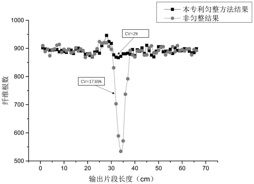
The invention relates to an auto-leveling method based on stable motion states of fibers in a drafting zone, the fibers in the drafting zone are divided into rear fibers, slow floating fibers, fast floating fibers and front fibers, and the distribution of the rear fibers in the drafting zone is obtained through statistics of a discrete drafting model. Supposing that the speed of slow floating fibers in the discrete drafting model is consistent with the speed of the rear roller all the time, the auto-leveling method comprises the steps that the speed of the rear roller is adjusted to be V2 (t) at the moment of T1 (t), and the speed of the rear roller is adjusted to be the original speed at the moment of T2 (t). According to the invention, when input uneven fibers move in a slow floating fiber state, the speed of the rear roller is adjusted to stabilize the motion states of various fibers in the drafting area, and the influence of the fluctuation of the number of input fibers on the stability of the motion states of the fibers in the drafting area is eliminated. And the optimal speed change starting time and the optimal speed change ending time of the rear roller are calculated by using the input non-uniform length, so that the fibers of the non-uniform part can be leveled, and the fibers of other parts cannot be influenced.

Description

technical field [0001] The invention belongs to the technical field of spinning and relates to an autoleveling method based on stable fiber movement state in a drafting zone. Background technique [0002] Autolevelling is a way to adjust the unevenness of the output by adjusting the roller speed and changing the drafting multiple when the number of input fibers changes during the drafting process. [0003] The traditional leveling method detects the change of the linear density of the input strands, and adjusts the speed of the front roller or the rear roller to change the drafting ratio to maintain the stability of the linear density of the output strands. However, the traditional leveling method is only a static scale model, which regards the fibers in the drafting area as a whole, ignoring the four processes that the fibers will go through: back fibers, slow floating fibers, fast floating fibers and front fibers. Therefore, the model obviously has the following two probl...

Claims


Application Information

Patent Timeline
IPC IPC(8): D01H5/38
CPCD01H5/38
Inventor 范居乐汪军李立轻朱方亮万贤福
Owner DONGHUA UNIV
Why Eureka
Try Eureka