
Antenna measurement device and radar test system

An antenna measurement and transmitting antenna technology, applied in the field of radar testing, can solve problems such as expensive, unsuitable for high-intensity, high-volume antenna testing, and complex maintenance, so as to reduce strong reflections, reduce uncertain displacement factors, and improve measurement The effect of precision

Active Publication Date: 2022-05-13
NANJING FALCON EYE ELECTRONIC TECH CO LTD
View PDF0 Cites 0 Cited by
  • Summary
  • Abstract
  • Description
  • Claims
  • Application Information

AI Technical Summary

Problems solved by technology

[0008] The invention provides an antenna measurement device and a radar test system, aiming to effectively solve the technical problems that the antenna far-field pattern measurement system in the prior art is expensive, complicated to maintain, and unsuitable for high-intensity and large-scale antenna tests

Method used


Image

  • Antenna measurement device and radar test system
  • Antenna measurement device and radar test system
  • Antenna measurement device and radar test system

Examples


Embodiment Construction

[0042] The following will clearly and completely describe the technical solutions in the embodiments of the present invention with reference to the drawings in the embodiments of the present invention. Apparently, the described embodiments are only some of the embodiments of the present invention, but not all of them. Based on the embodiments of the present invention, all other embodiments obtained by those skilled in the art without creative efforts fall within the protection scope of the present invention.

[0043]In the description of the present invention, it should be noted that, unless otherwise specified and limited, the term "and / or" in this article is only a description of the relationship between associated objects, indicating that there may be three relationships, for example, A and / or B may mean: A exists alone, A and B exist simultaneously, and B exists alone. In addition, the character " / " in this article, unless otherwise specified, generally indicates that the...


PUM


Abstract

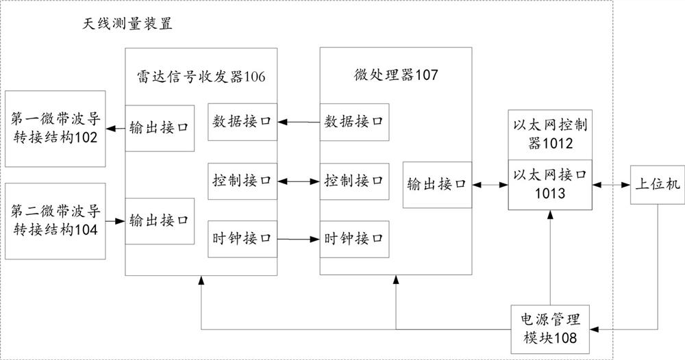
The invention discloses an antenna measurement device and a radar test system, wherein the device includes: a mixed board; a first microstrip-waveguide transition structure for connecting the transmitting antenna to be tested with the mixed board; a second micro Band-waveguide transfer structure, used to connect the receiving antenna under test with the mixed board; radar signal transceiver, used to output frequency-modulated continuous wave signal to the transmitting antenna under test, so that the transmitting antenna under test transmits FM to the target reflector Continuous wave signal, and the radar signal transceiver receives the echo signal from the target reflector received by the receiving antenna to be tested, and processes the echo signal to output a digital signal; the microprocessor is used to receive and process the digital signal and Upload the digital signal to the host computer. The technical solution provided by the invention can solve the technical problem that the antenna far-field pattern measurement system in the prior art is expensive and not suitable for high-intensity and large-scale antenna measurement.

Description

technical field [0001] The invention relates to the technical field of radar testing, in particular to an antenna measuring device and a radar testing system. Background technique [0002] In the prior art, the far-field pattern of some microwave antennas is measured in a microwave anechoic chamber, which requires the use of vector network analyzers, millimeter wave extensions, standard gain horn antennas, turntables, radio frequency cables and control computers and other components, the current antenna far-field pattern measurement system has the following technical problems. [0003] First of all, the vector network analyzer is the core instrument of the antenna remote pattern measurement system. Although the vector network analyzer has high measurement sensitivity and precision, it is expensive, maintenance is complicated, and there is a technical problem that only one antenna can be measured in a single test. , not suitable for high-intensity, high-volume antenna testin...

Claims


Application Information

Patent Timeline
Patent Type & Authority Patents(China)
IPC IPC(8): G01R29/10G01S7/40
Inventor 徐凌王冲冯友怀张燎
Owner NANJING FALCON EYE ELECTRONIC TECH CO LTD
Learn More