Automatically adjustable imager

An automatic adjustment, imager technology, applied in the field of imager, can solve the problems of insufficient dust protection, low work efficiency, insufficient clamping, etc., and achieve the effect of improving the efficiency of observation and collection

Active Publication Date: 2022-04-12
ANHUI POLYTECHNIC UNIV MECHANICAL & ELECTRICAL COLLEGE
View PDF6 Cites 0 Cited by
  • Summary
  • Abstract
  • Description
  • Claims
  • Application Information

AI Technical Summary

Problems solved by technology

[0005] The present invention provides an automatically adjustable imager, which is used to solve the technical problems of low working efficiency, insufficient clamping and insufficient dustproof protection in the existing equipment mentioned in the above background technology

Method used


Image

  • Automatically adjustable imager
  • Automatically adjustable imager
  • Automatically adjustable imager

Examples


Embodiment

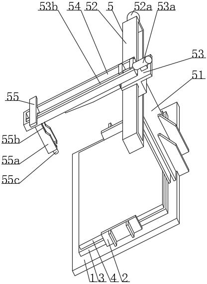
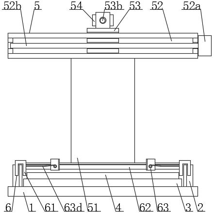
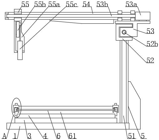
[0033] refer to Figure 1-7 , an automatically adjustable imager, comprising a base 1, the opposite sides of the base 1 are fixedly connected with baffles 2, the top of the base 1 is clamped with a marble table 3, and the top of the marble table 3 is fixedly connected with a loading The object table 4 is fixedly connected with the observation mechanism 5 at the rear end of the base 1 , and the positioning mechanism 6 is clamped at the top of the baffle plate 2 .

[0034] In this example, if figure 1 , figure 2 , image 3 , Figure 4 , Figure 6 and Figure 7 As shown, the observation mechanism 5 includes a bracket 51, the bottom end of the bracket 51 is fixedly connected with the rear end of the base 1, the top end of the bracket 51 is fixedly connected with a mounting frame 52, and the inner side of the mounting frame 52 is slidably connected with a mounting slide 53. The top of the slide seat 53 is fixedly connected with a guide frame 54, and the inner side of the gui...


PUM


Abstract

The invention provides an automatically adjustable imager which comprises a base, baffles are fixedly connected to the opposite sides of the base, a marble table is clamped to the top end of the base, an objective table is fixedly connected to the top end of the marble table, an observation mechanism is fixedly connected to the rear end of the base, and a positioning mechanism is clamped to the top ends of the baffles. The working position of the clamping seat is changed through the cooperation of the magnetic attraction block and the truss, and the clamping seat supports and positions a measured object, thereby preventing the vibration generated by the observation mechanism of the device in the working chamber from affecting the placement stability of the object on the surface of the objective table, improving the observation and collection efficiency of the device on the appearance structure data of the measured object, and improving the measurement precision. The problems that existing equipment is low in working efficiency, insufficient in clamping and insufficient in dustproof protection are solved.

Description

technical field [0001] The invention mainly relates to the field of video equipment, in particular to an automatically adjustable video equipment. Background technique [0002] As a measuring device, the automatic imager can realize the measurement of the contour size, surface shape and angle of various complex workpieces, and graph the measurement data, which will affect the need to fix the workpiece on the glass plate during the working process of the measuring instrument. on stage. [0003] The existing patent (notification number: CN109387146A) discloses a video measuring instrument, including a video measuring instrument body, which is connected to a PC terminal for enlarging the product and measuring the actual size of the product, wherein the video measuring instrument body includes a base , an image device, a column and a workbench, the image device is fixed on one side of the column, the workbench and the column are arranged on the top of the base, and the workbenc...

Claims


Application Information

Patent Timeline
Patent Type & Authority Applications(China)
IPC IPC(8): G01B11/00G01B11/24G01B11/26
CPCY02E10/50
Inventor 杨月异
Owner ANHUI POLYTECHNIC UNIV MECHANICAL & ELECTRICAL COLLEGE
Why Eureka
Try Eureka