
Portable mounting rack for electromechanical equipment

A technology for electromechanical equipment and mounting racks, which is applied to mechanical equipment, machines/supports, supporting machines, etc., can solve the problems of wasting time and delaying the maintenance progress of electromechanical equipment, and achieves speeding up maintenance progress, facilitating cleaning and maintenance, and saving disassembly. effect of time

Inactive Publication Date: 2022-04-12
ZHANGJIAJIE INST OF AERONAUTICAL ENG
View PDF0 Cites 0 Cited by
  • Summary
  • Abstract
  • Description
  • Claims
  • Application Information

AI Technical Summary

Problems solved by technology

[0004] The purpose of the present invention is to solve the problem that when the electromechanical equipment in the prior art is damaged, it is necessary to disassemble the connecting bolts between the mounting frame and the equipment and then repair the electromechanical equipment, which wastes a lot of time and delays the maintenance progress of the electromechanical equipment. A portable mounting frame for electromechanical equipment

Method used


Image

  • Portable mounting rack for electromechanical equipment
  • Portable mounting rack for electromechanical equipment
  • Portable mounting rack for electromechanical equipment

Examples


Embodiment Construction

[0019] The following will clearly and completely describe the technical solutions in the embodiments of the present invention with reference to the accompanying drawings in the embodiments of the present invention. Obviously, the described embodiments are only some, not all, embodiments of the present invention.

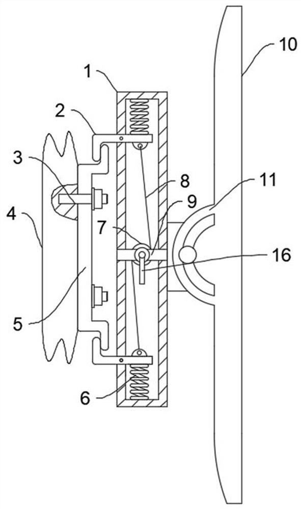
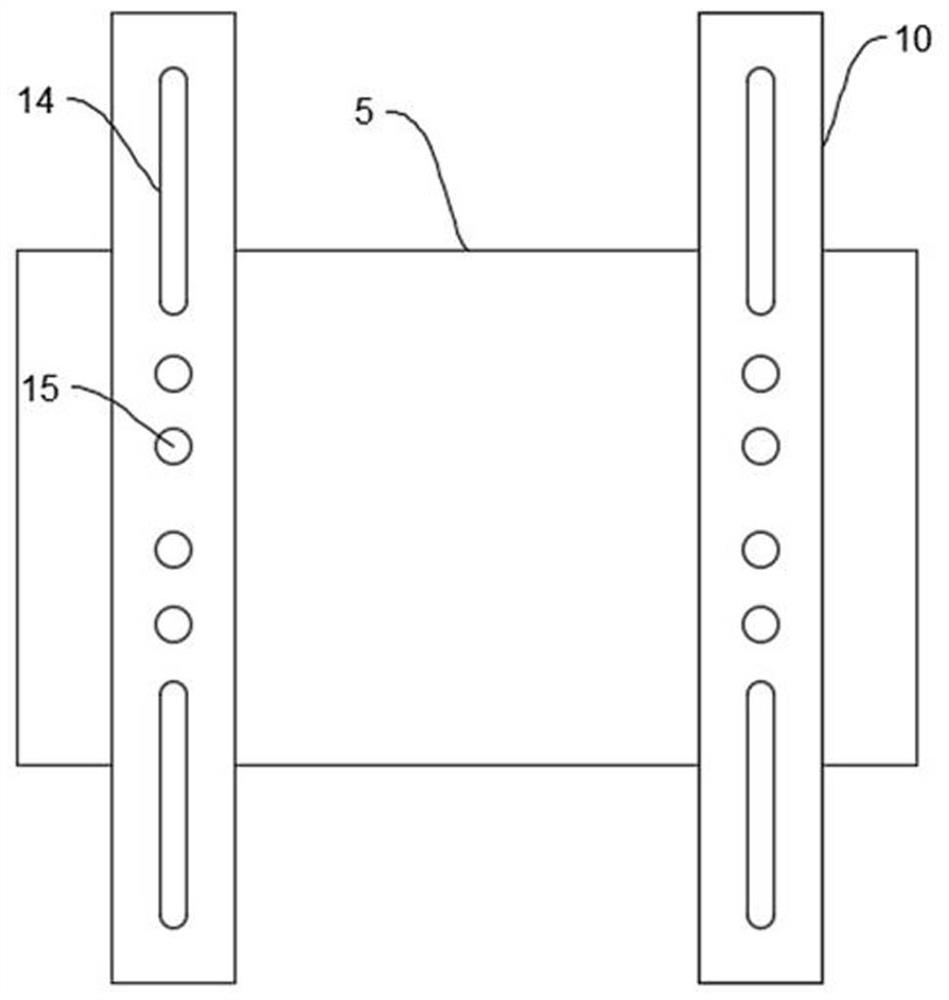
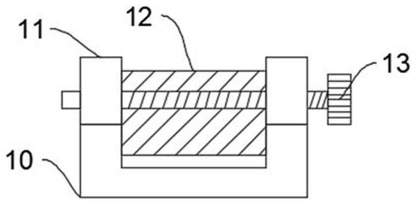
[0020] refer to Figure 1-3 , a portable mounting frame for electromechanical equipment, comprising a clamping box 1, a reset spring 6 is fixedly connected to the top of the clamping box 1, and a clamping rod 2 is fixedly connected to the bottom of the reset spring 6, and the cross-sectional shape of the clamping rod 2 is L-shaped, The middle position of the clamping rod 2 is fixedly connected to the left side of the clamping box 1;

[0021] The left end of the clamping rod 2 is clamped with a wall mounting frame 5, the right end of the wall mounting frame 5 is movably connected with a bolt 3, the left end of the bolt 3 is movably connected with a wall 4, and the mid...


PUM


Abstract

The invention discloses a portable mounting rack for electromechanical equipment, and relates to the technical field of electromechanical equipment.The portable mounting rack comprises a clamping box, a reset spring is fixedly connected to the top of the clamping box, a clamping rod is fixedly connected to the bottom of the reset spring, a wall mounting rack is clamped to the left end of the clamping rod, and a bolt is movably connected to the end face of the right side of the wall mounting rack; the left end of the bolt is movably connected with a wall body, and the middle position of the clamping box is fixedly connected with a fixed cross rod; the mounting rack connected with the wall body and the electromechanical equipment mounting rack are independent from each other, and the reset springs and the clamping rods at the two ends of the interior of the clamping box are matched with each other to clamp the electromechanical equipment mounting rack on the mounting rack connected with the wall body; and the rotating rod is rotated to drive the steel rope on the wire wheel to pull the clamping rod, so that the two mounting frames can be separated, the disassembly time of the electromechanical equipment is saved, and the maintenance progress of the electromechanical equipment is accelerated.

Description

technical field [0001] The invention relates to the technical field of electromechanical equipment, in particular to a portable mounting frame for electromechanical equipment. Background technique [0002] Equipment is usually a general term for material materials such as machinery, devices, and facilities that people need in production and life. Electromechanical equipment refers to equipment that uses mechanical and electronic technologies. Before the operation of electromechanical equipment, it is generally necessary to use a mounting frame to fix it. , to ensure the normal and stable operation of electromechanical equipment. [0003] The existing electromechanical equipment installation bracket uses bolts to fix itself on the wall, and then uses bolts to fix the electromechanical equipment on the bracket. When the electromechanical equipment is damaged, it is necessary to remove the connecting bolts and then repair the electromechanical equipment, which is a waste of tim...

Claims


Application Information

Patent Timeline
Patent Type & Authority Applications(China)
IPC IPC(8): F16M13/02F16M11/04F16M11/10
Inventor 余益志邵伟芹宋新华
Owner ZHANGJIAJIE INST OF AERONAUTICAL ENG
Learn More