
Polarizer and display device

A technology for display devices and polarizers, which is applied to identification devices, polarizing elements, televisions, etc., can solve the problems of display differences and low transmittance of polarizers, and achieve the effect of reducing display differences and increasing the amount of incoming light.

Pending Publication Date: 2022-04-08
HEFEI VISIONOX TECH CO LTD
View PDF0 Cites 1 Cited by
  • Summary
  • Abstract
  • Description
  • Claims
  • Application Information

AI Technical Summary

Problems solved by technology

However, the light transmittance of the polarizer is low. In order to improve the shooting quality of the camera assembly, it is necessary to increase the light transmittance of the area of ​​the polarizer corresponding to the camera assembly, and at the same time, it is necessary to solve the problem that the screen body corresponds to the light transmission area and the surrounding area. Issues with display discrepancies between display regions

Method used


Image

  • Polarizer and display device
  • Polarizer and display device
  • Polarizer and display device

Examples


Embodiment Construction

[0031] The following will clearly and completely describe the technical solutions in the embodiments of the application with reference to the drawings in the embodiments of the application. Apparently, the described embodiments are only part of the embodiments of the application, not all of them. Based on the implementation manners in this application, all other implementation manners obtained by persons of ordinary skill in the art without making creative efforts belong to the scope of protection of this application.

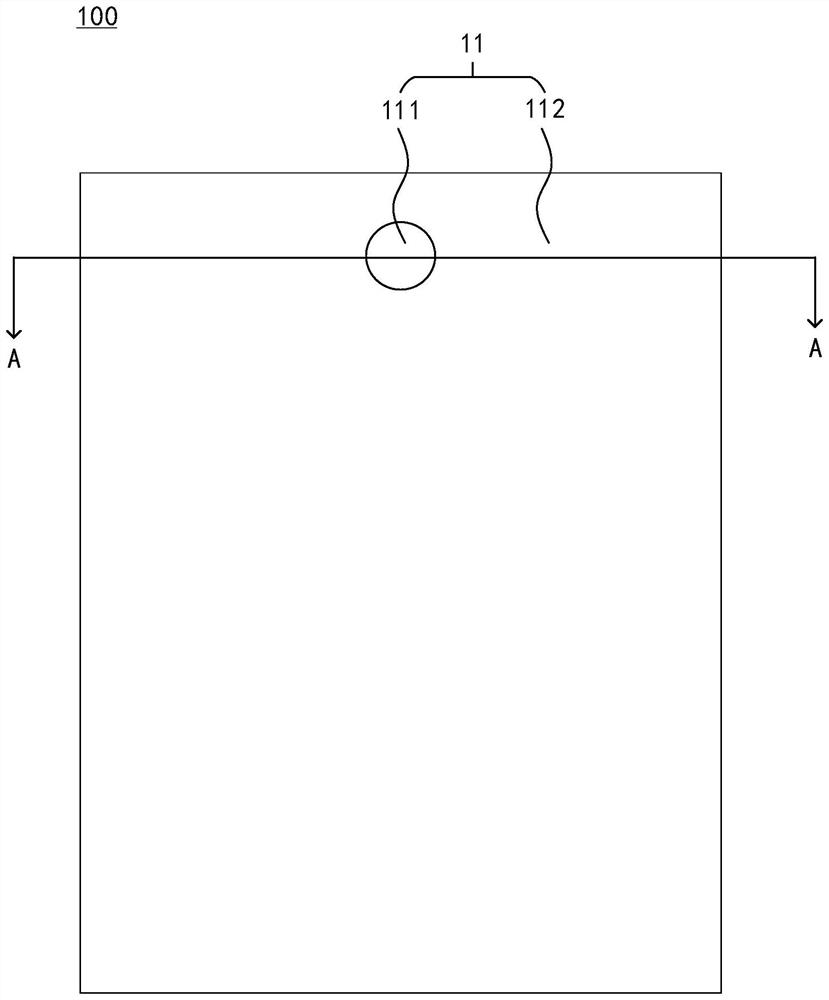
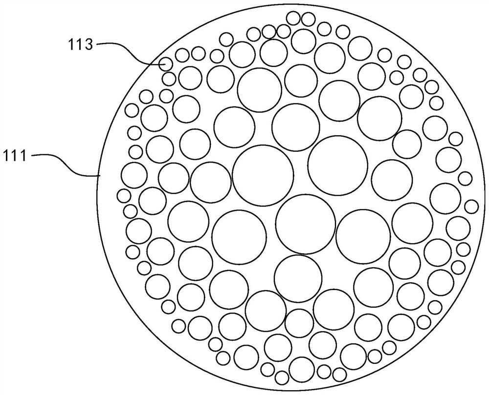
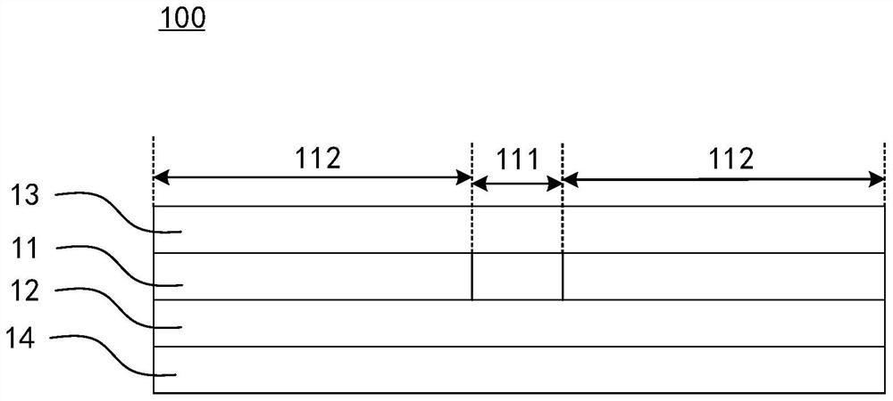
[0032] see Figure 1-Figure 3 , figure 1 It is a schematic structural diagram of an embodiment of a polarizer in the present application, figure 2 for figure 1 The enlarged schematic diagram of the first region in , image 3 for figure 1 The schematic cross-sectional view of the A-A direction in the middle, the polarizer 100 in this embodiment includes a linear polarizing film 11, and also includes a first supporting film 12, a second supporting film 13 an...


PUM


Abstract

The invention discloses a polaroid and a display device, and belongs to the technical field of display. The polarizer disclosed by the invention comprises a linear polarizing film, wherein the linear polarizing film comprises a first region and a second region surrounding the first region; wherein the first area is provided with a plurality of open pores, and in the direction from the center of the first area to the edge of the first area, the proportion of the open pore area in the unit area in the first area is gradually reduced, so that the average light transmittance of the linear polarizing film in the unit area is gradually reduced. The plurality of holes can enable more light to penetrate through the first area, and when the polaroid is subsequently applied to the display device, the camera assembly can be arranged corresponding to the first area, so that the light incoming amount of the camera assembly is improved. The average light transmittance of the linear polarizing film in unit area is gradually reduced from the center of the first area to the outside, so that the light transmittance of the part, closer to the second area, in the first area is closer to the second area, and the display difference of the display device corresponding to the first area and the second area can be reduced.

Description

technical field [0001] The present application relates to the field of display technology, in particular to a polarizer and a display device. Background technique [0002] As the screen-to-body ratio of the display device becomes higher and higher, a full-screen technology is gradually developed. In order to realize the full screen, the display device needs to arrange a camera component under the screen body. When the camera component is turned off, the screen above it displays normally. When the camera component is started, the screen above it needs to ensure sufficient light input. The display device is usually provided with a polarizer above the screen body to reduce the negative impact of ambient light on the display effect. However, the light transmittance of the polarizer is low. In order to improve the shooting quality of the camera assembly, it is necessary to increase the light transmittance of the area of ​​the polarizer corresponding to the camera assembly, and a...

Claims


Application Information

Patent Timeline
IPC IPC(8): G02B5/30G09F9/30H04N5/225
Inventor 王盼盼陈继峯
Owner HEFEI VISIONOX TECH CO LTD
Learn More