Continuous ink supply device for printer

A technology for ink supply devices and printers, applied in printing, etc., can solve problems affecting printing progress and output, affecting printing quality, etc., and achieve the effects of improving printing efficiency, convenient operation, and high reliability

Active Publication Date: 2022-04-08
BEIJING ZHONGDIAN YUANDE TECH CO LTD
View PDF9 Cites 1 Cited by
  • Summary
  • Abstract
  • Description
  • Claims
  • Application Information

AI Technical Summary

Problems solved by technology

An inlet is set on the main ink tank in the prior art, and it is sealed with an ink cartridge cover. The ink cartridge cover is provided with an ink outlet joint, an air intake joint and a liquid level sensor. If the ink in the main ink tank is insufficient, the following two methods are usually adopted: Ink replenishment: one way is to add ink to the main ink tank, and the other way is to replace the main ink tank; when adding ink, the ink tank cover needs to be unscrewed, and the various joints set on it should be removed at the same time. When replacing the main ink tank, it is also necessary to unplug the pipeline on the ink cartridge, and then reconnect after replacing the main ink tank. Both operations need to stop the printer so that there is enough time to connect the connector and the liquid level sensor. Avoid ink supply being affected, which will affect the printing progress and output, printing interruption may even affect the printing quality

Method used


Image

  • Continuous ink supply device for printer
  • Continuous ink supply device for printer
  • Continuous ink supply device for printer

Examples


Embodiment 1

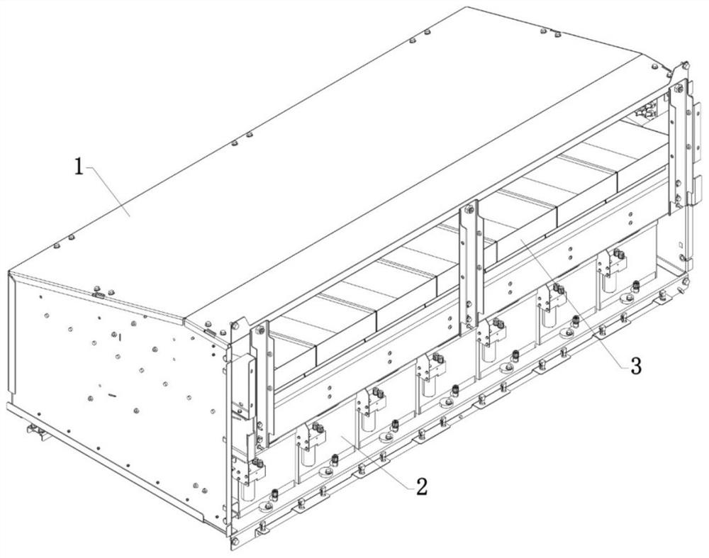
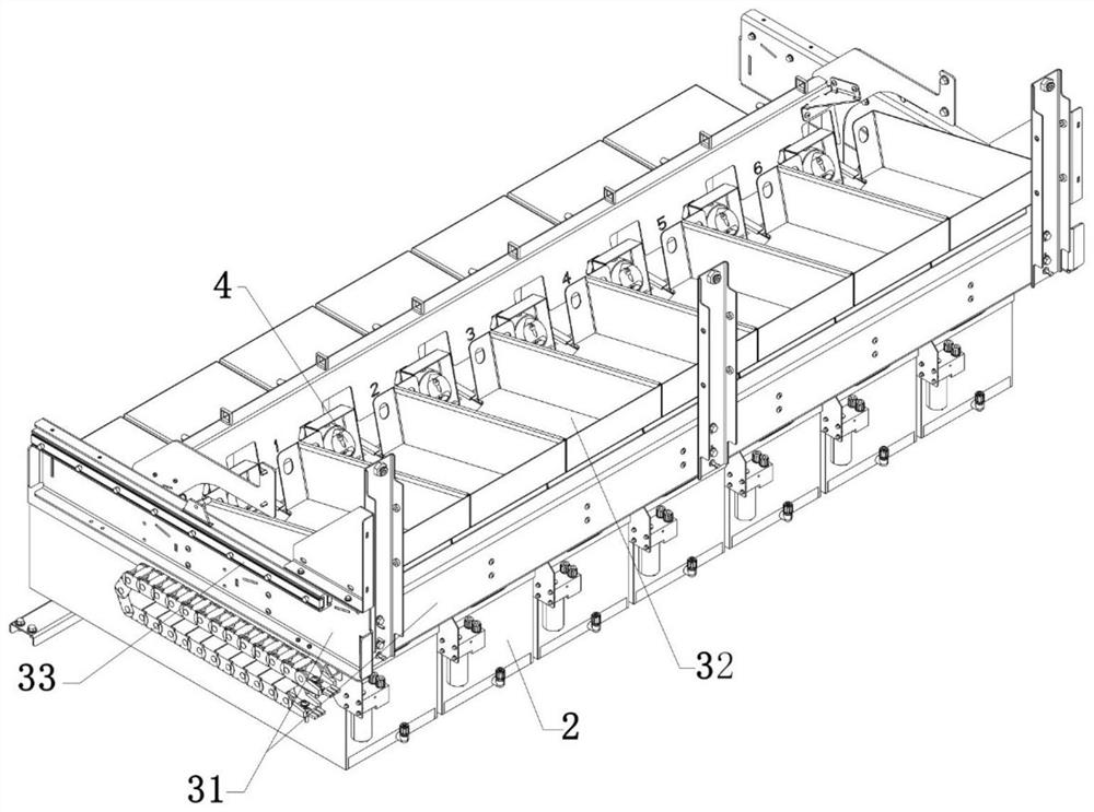
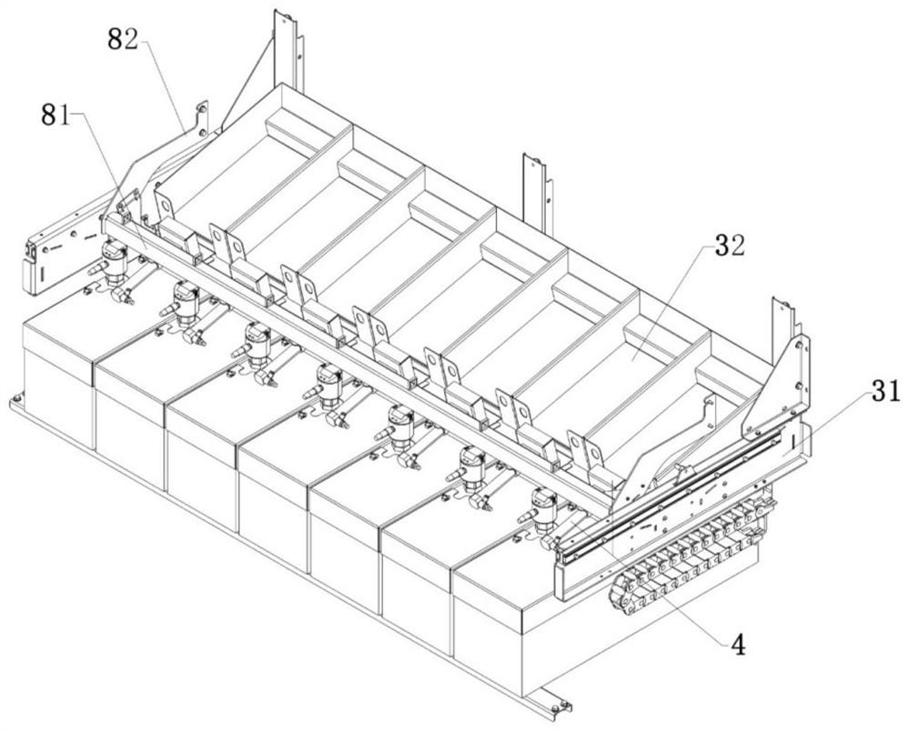
[0032] refer to Figure 1 to Figure 4 As shown, a continuous ink supply device for a printer is improved in that it includes an ink supply tank 1, a main ink tank 2 is provided at the bottom of the ink supply tank 1, and a liquid level is provided in the main ink tank 2. Sensor 23; an ink replenishment device 3 is installed above the main ink tank 2 in the ink supply tank 1, and the ink replenishment device 3 can move back and forth relative to the ink supply tank 1, and the ink replenishment device 3 includes a mounting frame 31, the installation frame 31 is equipped with a storage slot 32 corresponding to the position of the main ink tank 2, and the storage slot 32 is used to place the ink replenishment cartridge, and when the installation frame 31 is moved to the limit position , the position of the ink outlet of the ink replenishment ink cartridge placed on the accommodating tank 32 corresponds to the position of the ink inlet 211 of the main ink tank 2; a hole-breaking de...

Embodiment 2

[0038] On the basis of embodiment 1, with reference to Figure 9 and Figure 10 As shown, the main ink tank 2 includes a tank body 21 and an upper cover 22 that cover each other, the ink inlet 211 is arranged on the upper cover 22, and the lower end of the ink inlet 211 is provided with a chute 2111 .

[0039] Further, the opening direction of the chute 2111 faces away from the liquid level sensor 23 .

[0040] Further, the bottom of the tank body 21 is inclined, and the lower side of the bottom of the tank body 21 is provided with an ink outlet hole 221, and the outer port of the ink outlet hole 211 is provided with an ink outlet joint 24 .

[0041] Further, the bottom of the tank body 21 is provided with a groove 222 communicating with the ink outlet hole 211 , and the upper end of the groove 222 is provided with a filter layer 25 .

[0042]In this embodiment, the setting of the chute 2111 guides the flow of ink, preventing the ink from directly pouring onto the liquid l...

Embodiment 3

[0044] On the basis of embodiment 1 or 2, with reference to Figure 4 and Figure 5 As shown, an ink receiving tank 5 is arranged under the rear side of the accommodating tank 32 , and the ink receiving tank 5 is movably connected with the installation frame 31 and can move back and forth relative to the installation frame 31 .

[0045] Further, the left and right sides of the ink receiving tank 5 are respectively provided with connecting parts, and the ink receiving tank 5 is flexibly connected with the installation frame 31 through the connecting parts, and the connecting parts include The front and rear brackets 61 and rear brackets 62 fixedly connected to the front and rear sides of the groove 5 and the mounting frame 31 are provided with the front bracket 61 and the rear bracket 62 between the front bracket 61 and the rear bracket 62. The connecting column 63 is fixedly connected and passed through the ink receiving tank 5 , and a spring 64 is sleeved on the connecting c...


PUM


Abstract

The continuous ink supply device for the printer comprises an ink supply box, a main ink tank is arranged on the lower portion of the ink supply box, and a liquid level sensor is arranged in the main ink tank; an ink supplementing device is installed above a main ink tank in the ink supply box, the ink supplementing device can move back and forth relative to the ink supply box, the ink supplementing device comprises an installation frame, the installation frame is provided with a containing groove corresponding to the main ink tank in position, and the containing groove is used for containing an ink supplementing ink box. When the installation frame moves backwards to a limit position, an ink outlet of the ink supplementing ink box placed on the containing groove corresponds to an ink inlet of the main ink tank in position. The ink supply box is internally provided with a hole breaking device, and the hole breaking device is used for puncturing a sealing layer at an ink outlet of the ink supplementing ink box so that ink in the ink supplementing ink box can flow into the main ink tank. The ink supply device has the beneficial effects of guaranteeing continuous ink supply of the printing spray head, being convenient to operate, high in practicability and high in reliability.

Description

technical field [0001] The invention relates to the technical field of inkjet printing equipment, in particular to a continuous ink supply device for a printer. Background technique [0002] In order to ensure the continuous and stable supply of ink to the print nozzles in existing inkjet printers, secondary ink cartridges are often installed on the printing carriage. The ink flows from the main ink tank into the secondary ink cartridges, and then the secondary ink cartridges supply the ink to each print nozzle. The secondary ink box is connected with the negative pressure device, so that there is a constant negative pressure value in the secondary ink box to ensure the stability of ink supply; there is a liquid level sensor in the secondary ink box to detect the amount of ink in the secondary ink box , so that when the secondary ink tank is short of ink, ink can be replenished from the main ink tank to the secondary ink tank in time. An inlet is set on the main ink tank in...

Claims


Application Information

Patent Timeline
Patent Type & Authority Applications(China)
IPC IPC(8): B41J2/175
CPCB41J2/175
Inventor 单健王家远闫峂脱占贺单川
Owner BEIJING ZHONGDIAN YUANDE TECH CO LTD
Why Eureka
Try Eureka