
Robot positioning calibration charging device

A robot positioning and charging device technology, applied in circuit devices, battery circuit devices, coupling devices, etc., can solve the problems of charging column wear and inaccurate positioning, and achieve the effects of avoiding wear, accurate connection, and delaying connection time.

Pending Publication Date: 2022-03-25
牛坤
View PDF0 Cites 0 Cited by
  • Summary
  • Abstract
  • Description
  • Claims
  • Application Information

AI Technical Summary

Problems solved by technology

[0004] Aiming at the deficiencies of the prior art, the present invention provides a robot positioning calibration charging device, which solves the problem of inaccurate positioning and wear on its charging column

Method used


Image

  • Robot positioning calibration charging device
  • Robot positioning calibration charging device
  • Robot positioning calibration charging device

Examples


Embodiment Construction

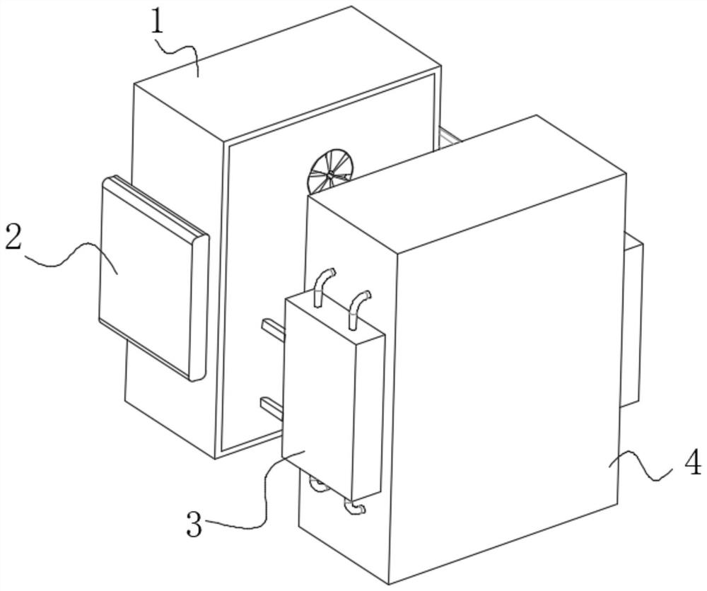
[0023] use Figure 1-Figure 6 A charging device for positioning and calibrating a robot according to an embodiment of the present invention is described as follows.

[0024] Such as Figure 1-Figure 6 As shown, a robot positioning calibration charging device according to the present invention includes a connecting block 1; The right end is fixedly connected, the front of the snap-in block 2 is provided with a charging block 4, the two ends of the charging block 4 are symmetrically provided with a snap-in slot 3, and the left end of the charging block 4 is fixedly connected with the right end of the snap-in slot 3, and the snap-in slot is set The purpose of 3 is to reduce the wear efficiency of this kind of robot positioning calibration charging device.

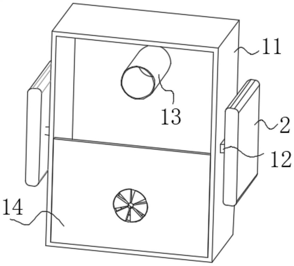
[0025] The charging block 1 includes a main body 11. A charging tank 13 is symmetrically arranged inside the main body 11, and the inner wall of the main body 11 is fixedly connected with the bottom of the charging tank 13. ...


PUM


Abstract

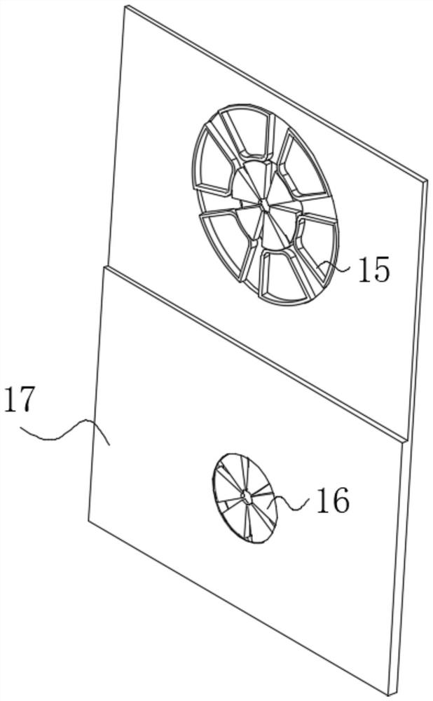
The invention belongs to the technical field of robot equipment, and particularly relates to a robot positioning calibration charging device which comprises a power connection block. Clamping blocks are symmetrically arranged at the two ends of the power connection block, the left end of the power connection block is fixedly connected with the right ends of the clamping blocks, a charging block is arranged on the front face of the clamping blocks, clamping grooves are symmetrically formed in the two ends of the charging block, the left end of the charging block is fixedly connected with the right ends of the clamping grooves, and the charging block comprises a main body; charging grooves are symmetrically formed in the main body, the inner wall of the main body is fixedly connected with the bottoms of the charging grooves, a partition plate is arranged on the front face of the main body, the outer surface of the partition plate is fixedly connected with the inner wall of the main body, mounting blocks are symmetrically arranged at the two ends of the main body, and the right end of the main body is fixedly connected with the left ends of the mounting blocks. The partition plate comprises a plate body, extrusion elastic pieces are symmetrically arranged in the plate body, and the inner wall of the plate body is fixedly connected with the bottoms of the extrusion elastic pieces.

Description

technical field [0001] The invention belongs to the technical field of robot equipment, in particular to a robot positioning calibration charging device. Background technique [0002] The current intelligent sweeping robot usually has the function of automatically returning to charge, and the common charging structure of the sweeping robot on the market is mostly to use the charging pile and the charging contact set at the bottom of the robot to rely on the guidance of the navigation system to accurately move to the top of the charging contact. Electrical connection and charging, but this electrical connection method mainly uses the weight of the sweeping robot itself to ensure the pressing of the bottom contact and the charging pile contact. In the case of unreliable connection, at the same time, when docking with the charging pile on the return trip, the positioning and calibration speed is slow, and it is easy to collide with the charging pile and cause damage. A robot po...

Claims


Application Information

Patent Timeline
Patent Type & Authority Applications(China)
IPC IPC(8): H01R13/631H01R13/639H01R13/64H02J7/00
CPCH01R13/631H01R13/639H01R13/64H02J7/0045
Inventor 牛坤
Owner 牛坤
Learn More