Supporting device in concrete wall concealed distribution box and use method of supporting device

A technology for concrete walls and support devices, which is applied to switch devices, pillars, electrical components, etc., can solve the problems of large blocking workload, generation of garbage, and displacement of boxes, so as to reduce garbage generation and improve accuracy. , the effect of quick installation

Pending Publication Date: 2022-03-22
MCC TIANGONG GROUP
View PDF0 Cites 1 Cited by
  • Summary
  • Abstract
  • Description
  • Claims
  • Application Information

AI Technical Summary

Problems solved by technology

[0004] The problem to be solved by the present invention is that the construction method of the traditional distribution box in the prior art has a large amount of plugging work in the later stage, the deformation or damage of the box body caused by extrusion affects the function, the box body shifts and generates garbage, and the cost is relatively high. , to provide a support device and its use method in a concrete wall buried power distribution box, which reduces the influence of construction disturbance on the position of the power distribution box, reduces the workload in the later period, improves the pre-embedded positioning accuracy of the power distribution box, and has a better supporting effect Well, to reduce the risk of waste generation and distribution box being squeezed and deformed, the traditional construction method can be improved, it can adapt to the construction of distribution boxes of various sizes, and realize rapid installation, disassembly and multiple turnover use

Method used


Image

  • Supporting device in concrete wall concealed distribution box and use method of supporting device
  • Supporting device in concrete wall concealed distribution box and use method of supporting device
  • Supporting device in concrete wall concealed distribution box and use method of supporting device

Examples


Embodiment Construction

[0034] Embodiments of the present invention are described in detail below, examples of which are shown in the drawings, wherein the same or similar reference numerals designate the same or similar elements or elements having the same or similar functions throughout. The embodiments described below by referring to the figures are exemplary and are intended to explain the present invention and should not be construed as limiting the present invention.

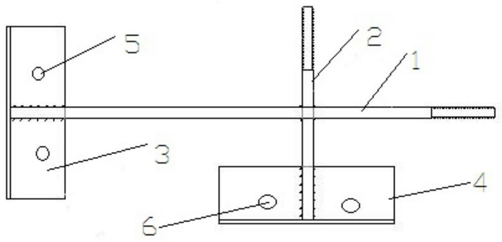
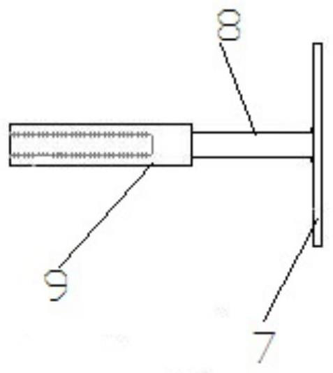
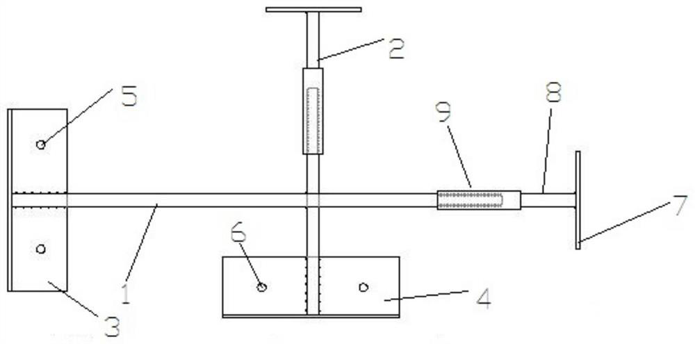
[0035] Please see attached figure 1 - attached Figure 4 , an embodiment of the present invention provides a support device in a power distribution box buried in a concrete wall, including:

[0036] The fixed side member is used for fixed connection with the formwork;

[0037] The adjustable side member is used for connecting with the fixed side member and adjusting the internal support of the internal support device.

[0038] Specifically, the fixed side members include:

[0039] Horizontal fixed rod 1 and vertical fixed rod...


PUM


Abstract

The invention provides a support device in a concrete wall buried distribution box and a use method thereof, and the device comprises a fixed side member which is used for being fixedly connected with a template; the adjustable side component is used for being connected with the fixed side component and conducting inner supporting adjustment on the inner supporting device. The supporting device has the beneficial effects that the problems that according to a traditional distribution box construction mode, the later plugging workload is large, a box body is extruded to deform or be damaged, the function is affected, the box body shifts, garbage is generated, and the cost is high are solved, and the supporting device in the concrete wall hidden-buried distribution box and the using method thereof are provided. The influence of construction disturbance on the position of the distribution box is reduced, the later workload is reduced, the pre-embedding positioning accuracy of the distribution box is improved, the supporting effect is better, garbage generation and the risk that the distribution box is extruded and deformed are reduced, a traditional construction method can be improved, and the method can adapt to construction of distribution boxes of various sizes; and rapid installation, disassembly and repeated turnover use are realized.

Description

technical field [0001] The invention belongs to the technical field of building construction, and in particular relates to a supporting device in a power distribution box buried in a concrete wall and a method for using the same. Background technique [0002] In the current building construction, there are three existing traditional distribution box construction methods: First, in the main construction stage of the distribution box, first use wooden formwork to nail the box to make the reserved hole formwork, remove it after pouring, and then in the plastering stage Install the box body of the distribution box, and finally seal the gap between the box body and the reserved hole; second, the finished distribution box is reserved and embedded in the main stage, without support inside the box body, and the positioning of the box body is determined by the extrusion force of the template and The positioning is carried out by binding steel bars on the wall; the third is that the f...

Claims


Application Information

Patent Timeline
Patent Type & Authority Applications(China)
IPC IPC(8): E04G15/06E04G25/06H02B3/00
CPCE04G15/061E04G25/065H02B3/00
Inventor 田盛刘天荣
Owner MCC TIANGONG GROUP
Why Eureka
Try Eureka