
Silicon carbide MOSFET device high-temperature gate bias test method and system

A high-temperature gate bias, silicon carbide technology, which is applied in the direction of single semiconductor device testing, instruments, measuring devices, etc., can solve the problems of inability to test the reliability of silicon carbide MOSFET devices, and achieve the effect of reasonable reliability testing.

Pending Publication Date: 2022-03-18
ZHUZHOU CRRC TIMES SEMICON CO LTD
View PDF0 Cites 0 Cited by
  • Summary
  • Abstract
  • Description
  • Claims
  • Application Information

AI Technical Summary

Problems solved by technology

[0004] However, with the wide application of silicon carbide MOSFET devices in different fields, there are many kinds of driving circuits. The driving voltage output by the driving circuit is no longer a single constant voltage +20V / -20V, and there are various driving voltages in different application scenarios. , because different driving voltages have different effects on the reliability of the device, according to the current international standards, it has been impossible to conduct a comprehensive and reasonable reliability test on silicon carbide MOSFET devices

Method used


Image

  • Silicon carbide MOSFET device high-temperature gate bias test method and system
  • Silicon carbide MOSFET device high-temperature gate bias test method and system
  • Silicon carbide MOSFET device high-temperature gate bias test method and system

Examples


Embodiment Construction

[0037] In order to make the purpose, technical solutions and advantages of this specification more clear, the following will further describe this specification in detail in combination with specific embodiments and with reference to the accompanying drawings.

[0038]It should be noted that, unless otherwise defined, the technical terms or scientific terms used in the embodiments of the present specification shall have ordinary meanings understood by those skilled in the art to which the present disclosure belongs. "First", "second" and similar words used in the present disclosure do not indicate any order, quantity or importance, but are only used to distinguish different components. "Comprising" or "comprising" and similar words mean that the elements or items appearing before the word include the elements or items listed after the word and their equivalents, without excluding other elements or items. Words such as "connected" or "connected" are not limited to physical or m...


PUM


Abstract

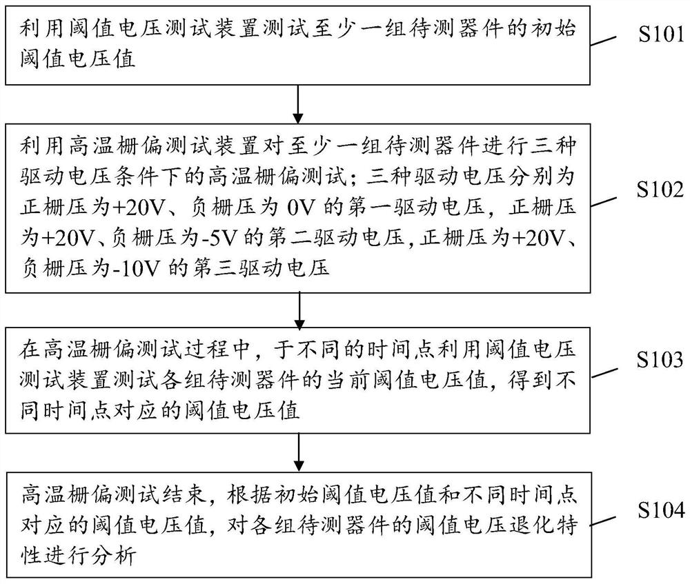
The embodiment of the invention provides a silicon carbide MOSFET device high-temperature gate bias test method and system. The method comprises the steps that a threshold voltage test device is used for testing the initial threshold voltage value of at least one set of devices to be tested; performing high-temperature gate bias test on the to-be-tested device under three driving voltage conditions by using the high-temperature gate bias test device; the three driving voltages are respectively + 20V / 0V, + 20V / -5V and + 20V / -10V; in the high-temperature gate bias test process, the threshold voltage test device is used for testing the current threshold voltage value of the device to be tested at different time points, and the threshold voltage values corresponding to the different time points are obtained; and after the high-temperature gate bias test is finished, analyzing the degradation characteristic of the threshold voltage according to the initial threshold voltage value and the threshold voltage values corresponding to different time points. According to the invention, the actual working condition of the device is fully considered, and the comprehensive reliability test can be carried out on the silicon carbide MOSFET device.

Description

technical field [0001] This specification relates to the technical field of electronic devices, in particular to a high temperature gate bias test method and system for silicon carbide MOSFET devices. Background technique [0002] Silicon carbide MOSFET device is a semiconductor device that can meet the application requirements under high temperature, high pressure and high frequency conditions, and has a wide range of applications in high-speed rail, smart grid, new energy vehicles and other fields. [0003] Before silicon carbide MOSFET devices leave the factory, reliability tests are required to ensure the performance and reliability of the devices. At present, the reliability test standards for silicon carbide MOSFET devices are international standards IEC 60747-9: 1998 and JEDEC JESD-55A108C, both of which are high temperature gate bias test standards for silicon carbide MOSFET devices. The test conditions specified in the standards are: test temperature At 150°C, the ...

Claims


Application Information

Patent Timeline
IPC IPC(8): G01R31/26
CPCG01R31/2628G01R31/2621
Inventor 石帮兵李诚瞻丁杰钦赵艳黎陈喜明戴小平
Owner ZHUZHOU CRRC TIMES SEMICON CO LTD
Learn More