
Bidirectional laser welding auxiliary jig

A laser welding, bidirectional technology, used in laser welding equipment, welding equipment, manufacturing tools and other directions, can solve the problem of low efficiency of cell welding fixture replacement, to improve the efficiency beat, convenient and simple operation, and change the efficiency high effect

Pending Publication Date: 2022-03-18
铭镭激光智能装备(河源)有限公司
View PDF0 Cites 0 Cited by
  • Summary
  • Abstract
  • Description
  • Claims
  • Application Information

AI Technical Summary

Problems solved by technology

[0004] The invention aims to improve the problem of low efficiency of the current electric core welding jig, improve the compatibility and flexibility of the electric core welding jig, thereby improving the welding production efficiency and tempo

Method used


Image

  • Bidirectional laser welding auxiliary jig
  • Bidirectional laser welding auxiliary jig
  • Bidirectional laser welding auxiliary jig

Examples


Embodiment 1

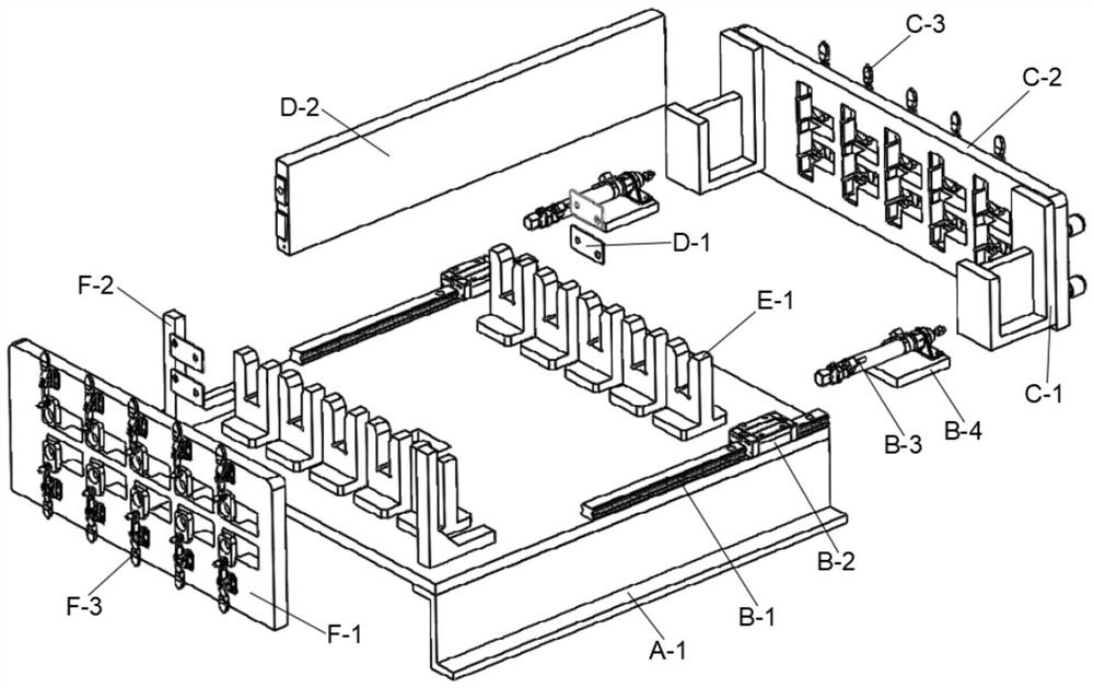
[0021] Embodiment one, with reference to the specification attached figure 1 , a bidirectional laser welding auxiliary jig, including a jig main body and a welding cell D, the jig main body includes a welding mechanism, the welding mechanism is used for horizontally welding the welding cell D, and the welding mechanism includes a bracket assembly A, a horizontal tensioning assembly B. The movable end C of the horizontal welding jig, the cell positioning slot E and the fixed end F, the bracket assembly A includes the platform frame A-1, the horizontal tensioning assembly B includes the first slide rail B-1 and the sliding installation on the second The first slider B-2 on a slide rail B-1, the first slider B-2 is fixed with a pressing actuator fixing block B-4, and the top of the pressing actuator fixing block B-4 is fixedly installed with The horizontal clamping actuator B-3, the movable end C of the horizontal welding fixture includes the clamping plate C-2, the fixed end F i...

Embodiment 2

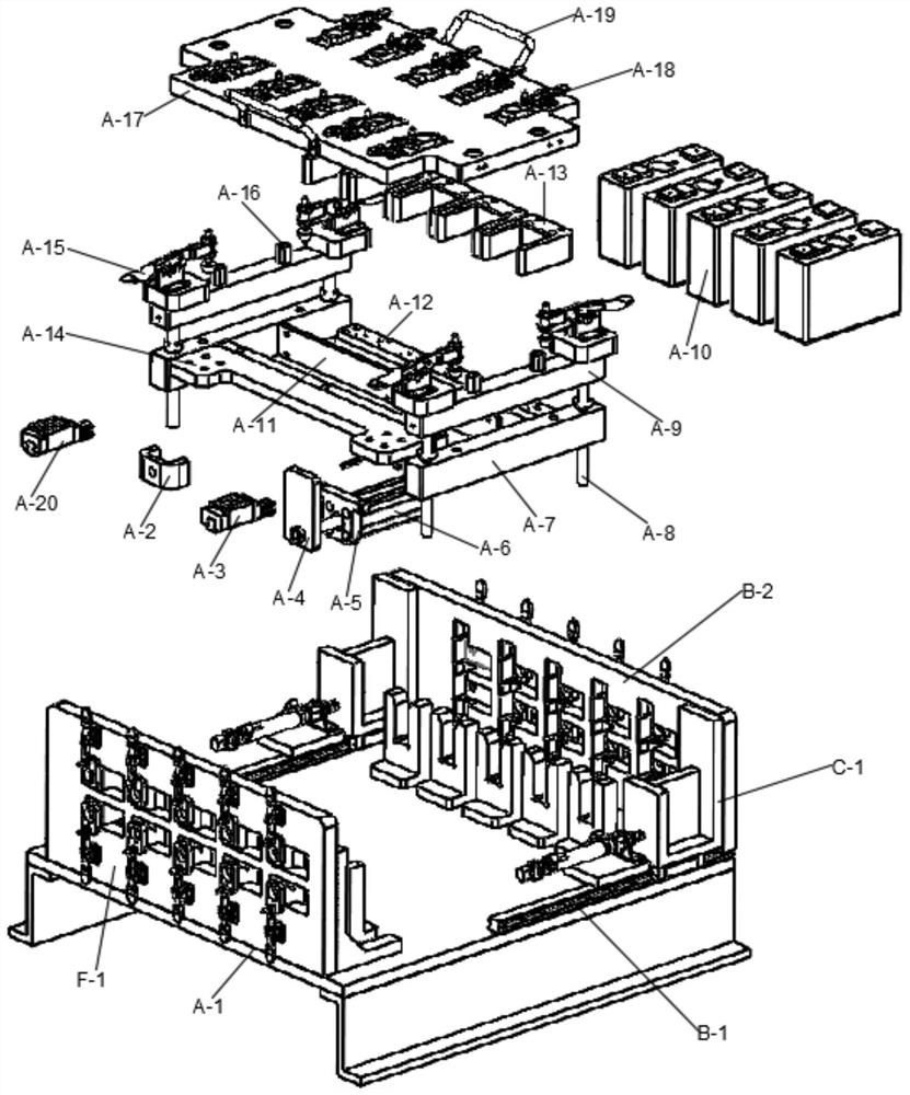
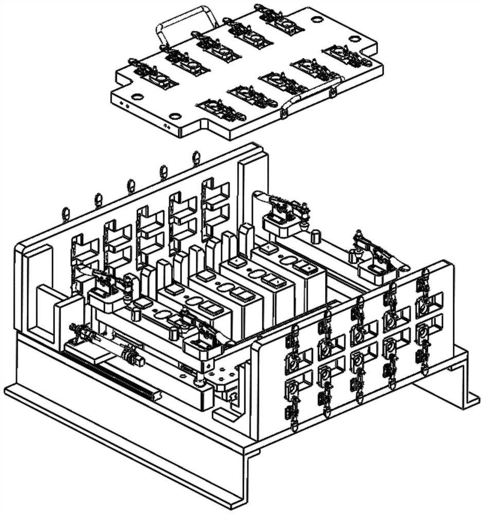
[0022] Embodiment two, with reference to the appended figure 2, a bidirectional laser welding auxiliary jig, including a jig main body and a welding cell D, the jig main body includes a welding mechanism, including a welding mechanism for vertically welding the welding cell D, the welding mechanism includes a bracket assembly A, a horizontal tensioning Component B, the movable end C of the horizontal welding fixture, the cell positioning slot E and the fixed end F, the bracket component A includes the platform frame A-1, the horizontal tensioning component B includes the first slide rail B-1 and is slidably installed on The first slider B-2 on the first slide rail B-1, the first slider B-2 is fixed with the pressing actuator fixing block B-4, and the top of the pressing actuator fixing block B-4 is fixed and installed There is a horizontal clamping actuator B-3, the movable end C of the horizontal welding jig includes a clamping plate C-2, and the fixed end F includes a cell ...


PUM


Abstract

The invention discloses a bi-directional laser welding auxiliary jig, and relates to the technical field of laser welding equipment, the bi-directional laser welding auxiliary jig comprises a jig main body and a welding battery cell, the jig main body comprises a welding mechanism, and the welding mechanism is used for horizontally welding the welding battery cell; the welding mechanism comprises a support assembly, a horizontal tensioning assembly, a horizontal welding jig movable end, a battery cell positioning clamping groove and a fixed end, the support assembly comprises a platform rack, the horizontal tensioning assembly comprises a first sliding rail and a first sliding block installed on the first sliding rail in a sliding mode, a pressing execution piece fixing block is fixed to the first sliding block, and the pressing execution piece fixing block is fixed to the platform rack. And a horizontal pressing execution piece is fixedly mounted at the top of the pressing execution piece fixing block. Two sets of positioning structures are adopted and are the horizontal welding positioning mechanism and the vertical welding positioning mechanism correspondingly. Welding paths in two different directions can be compatible in design, operation is convenient and easy, remodeling efficiency is high, and laser welding efficiency and takt are improved.

Description

technical field [0001] The invention relates to the technical field of laser welding equipment, in particular to a bidirectional laser welding auxiliary jig. Background technique [0002] Laser welding has been rapidly promoted in various industries due to its advantages of high welding efficiency, high precision, no pollution, and small heat-affected zone. Especially in the field of new energy cell welding is widely used. At present, most of the welding jigs used in new energy batteries are designed for general purpose according to the similar shape of the battery cells. For those with large differences in the appearance and structure of the batteries, additional welding jigs are equipped. The design will not only increase the production cost of the fixture, but also increase the time for fixture changeover and reduce production efficiency; the present invention can realize the compatibility of differentiated cell fixtures, improve the flexibility of fixture changeover, an...

Claims


Application Information

Patent Timeline
Patent Type & Authority Applications(China)
IPC IPC(8): B23K26/70B23K26/21
CPCB23K26/702B23K26/21
Inventor 李朝阳彭文齐刘威王志伟刘俊
Owner 铭镭激光智能装备(河源)有限公司
Learn More