
System and method for regulating switching converter

A technology of converters and switches, which is applied in the field of regulating switching converters, and can solve problems such as unstable states of switching converters

Pending Publication Date: 2022-03-15
SIEMENS AG
View PDF1 Cites 0 Cited by
  • Summary
  • Abstract
  • Description
  • Claims
  • Application Information

AI Technical Summary

Problems solved by technology

In this case, the turn-on behavior of the switching element may lead to an unstable state of regulation of the output voltage of the switching converter, thereby forcing the pulse-modulated switching regulator unit to be continuously between two consecutive valleys, for example at Jumping back and forth between the third and fourth troughs in an uncontrolled manner

Method used


Image

  • System and method for regulating switching converter
  • System and method for regulating switching converter
  • System and method for regulating switching converter

Examples


Embodiment Construction

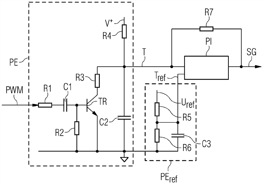
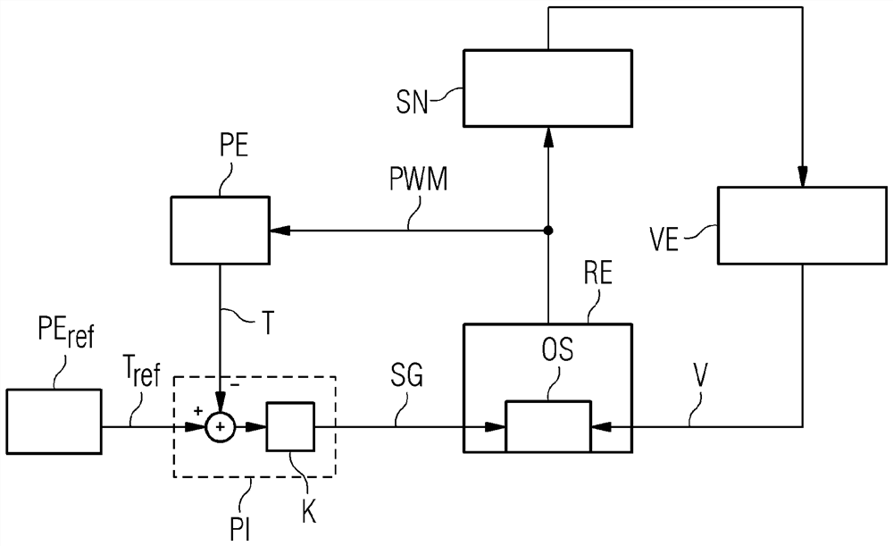
[0033] figure 1 A system according to the invention for regulating a quasi-resonantly switched switching converter SN is shown exemplarily and in a schematic manner. The system includes a switching converter SN with at least one switching element, which is actuated by means of a rectangular switching signal PWM. In this case, the switch-on time of the switching element is predetermined, for example, by means of a rising edge of the rectangular switching signal PWM. In the regulated state of switching converter SN, the switching elements are usually switched with a predetermined, stable switching frequency. This stable switching frequency or the associated period duration is predetermined by the dimensioning of switching converter SN, in particular the inductance and capacitance, and the efficiency to be achieved.

[0034] To generate the switching signal PWM, the system according to the invention has a switching regulator unit RE, which is designed, for example, as a pulse-w...


PUM


Abstract

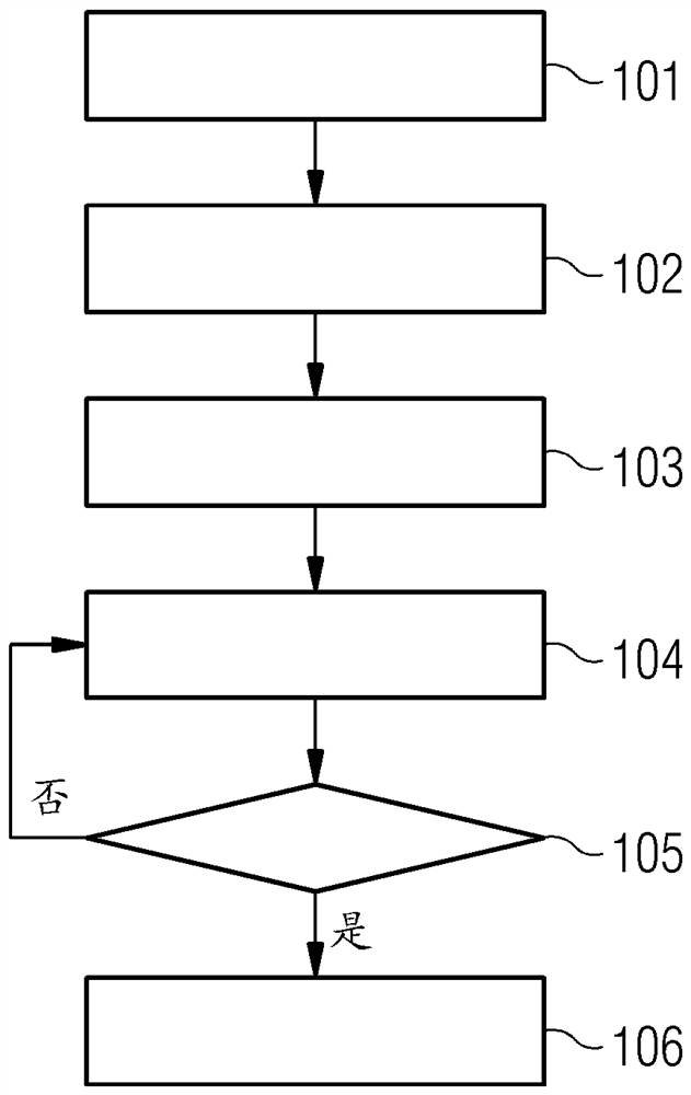
Systems and methods for regulating a switching converter. The invention relates to a method for regulating a switching converter having at least one switching element, the switching converter being operated in quasi-resonant operation and the switching element being switched in the regulated state of the switching converter at a predetermined stable switching frequency. The switching-on time of the switching element is specified by a switching signal of the switching regulator unit, which is generated by reaching or exceeding a switching-on threshold value by a zigzag signal loaded with a trough identification signal. The current period duration of the switching signal is determined by the unit for detecting the period duration, and the current period duration is compared by the regulator unit with a predetermined reference period duration of the period duration reference unit. From this comparison, a control variable is generated by the regulator unit, by means of which the distance between the zigzag signal and the switching threshold value is varied until the achievement of a stable switching frequency is confirmed by means of the determined current period duration.

Description

technical field [0001] The object (gegenständlich) invention relates generally to the field of electronic technology, in particular to the field of power electronics and power electronic circuits. In particular, the invention relates to a method and a system for regulating a switching converter having at least one switching element, wherein the switching converter is operated in quasi-resonant operation and the at least one switching element of the switching converter is in a switching The regulated state of the converter is switched with a predetermined stable switching frequency. In this case, the switch-on time of the switching element is predetermined by the switching signal of the switching regulator unit, which is generated by the saw-tooth signal reaching or exceeding the switch-on threshold. In this case, a valley detection signal is applied to the saw-tooth signal, so that the switching-on time of at least one switching element falls within a valley of the oscillatin...

Claims


Application Information

Patent Timeline
Patent Type & Authority Applications(China)
IPC IPC(8): H02M3/157
CPCH02M3/157H02M3/156H02M3/33507H02M1/0058Y02B70/10H02M1/0003
Inventor J·哈拉克
Owner SIEMENS AG
Learn More