
Rotary drilling rig power head structure with buffer mechanism

A buffer mechanism and buffer structure technology, applied in the direction of impact drilling, rotary drilling, drilling equipment, etc., can solve problems such as increasing the risk of motor damage, and achieve the effect of increasing the applicable range and enhancing protection.

Inactive Publication Date: 2022-03-11
徐州腾宇回转支承制造有限公司
View PDF0 Cites 0 Cited by
  • Summary
  • Abstract
  • Description
  • Claims
  • Application Information

AI Technical Summary

Problems solved by technology

[0004] But when the drill bit is working, it often needs to be raised and lowered. When the inside of the drill bit is filled with mud, it needs to be lifted up to clean it. As the power box rises, the drill bit comes to the ground. At that time, the driver will pass through the console. Controlling the power box, we can always find at the scene that when the driver is unloading the drill bit, the drill bit always rotates forward and reverse, and there is a sound around the power box. It is because the motor in the power box is overloaded for a period of time. The motor drives the drive shaft to rotate, and then the drive shaft drives the drill bit to rotate. When the motor is in forward and reverse rotation for a long time, the radial pressure on the motor shaft will increase. Therefore, when unloading, let the motor rotate forward and reverse to increase Increases the risk of motor damage, so it needs to be improved

Method used


Image

  • Rotary drilling rig power head structure with buffer mechanism
  • Rotary drilling rig power head structure with buffer mechanism
  • Rotary drilling rig power head structure with buffer mechanism

Examples


Embodiment

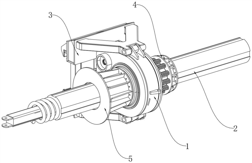
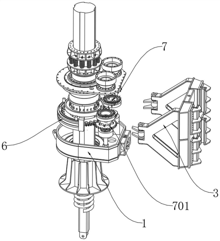
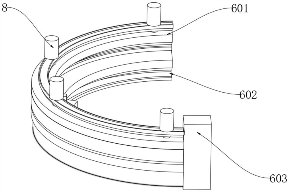
[0026] Example: such as Figure 1 to Figure 7 As shown, the present invention provides a rotary drilling power head structure with a buffer mechanism, including a power box 1, a radial buffer structure 6 arranged inside the power box 1, a driving force main shaft 9 is arranged at the center of the power box 1, The driving force main shaft 9 is sleeved with a gear set that is mutually locked with the radial buffer structure 6; the radial buffer structure 6 includes an upper chute 601 arranged on the inner ring of the power box 1, which The lower chute 602 below 601, the first gear clip 13 sliding inside the upper chute 601, and the second gear clip 14 sliding in the inner cavity of the lower chute 602, the upper chute 601 and the lower chute Both ends of 602 are equipped with magnets 603. The first gear bar 13 is provided with a pair of first opposite magnets 15 to slide inside the upper chute 601. The second gear bar 14 is provided with a pair of second magnets. The opposite ...


PUM


Abstract

The invention discloses a rotary excavating drill power head structure with a buffer mechanism, and belongs to the field of engineering equipment, the rotary excavating drill power head structure comprises a power box and a radial buffer structure arranged in the power box, the center of the power box is provided with a driving force main shaft, and the driving force main shaft is sleeved with a gear set locked with the radial buffer structure; the radial buffering structure comprises an upper-layer sliding groove formed in the inner ring of the power box, a lower-layer sliding groove formed below the upper-layer sliding groove, a first gear clamping strip sliding in the upper-layer sliding groove and a second gear clamping strip sliding in an inner cavity of the lower-layer sliding groove, and magnets are installed at the two common ends of the upper-layer sliding groove and the lower-layer sliding groove. The internal structure of the power box is improved, so that the drill bit can rotate back and forth only by intermittent forward rotation in the operation process of the motor, the upper-layer sliding groove and the lower-layer sliding groove are driven by the air cylinder to press downwards, the driving force main shaft stops, the drill bit can rotate forwards and backwards under the driving of the magnet, and the existing defects are overcome.

Description

technical field [0001] The invention relates to the technical field of building construction production equipment, in particular to a rotary drilling power head structure with a buffer mechanism. Background technique [0002] Rotary drilling is a construction technology suitable for hole-forming operations in building foundation engineering. It is widely used in foundation construction projects such as municipal construction, highway bridges, high-rise buildings, etc., and is suitable for dry (short spiral) or Wet (rotary bucket) and rock formation (core drill) hole forming operations. [0003] When it is working, due to the weight between the drill and the drill string, when the drill bit rises and falls, a buffer mechanism is generally installed outside or on the top of the power box. This buffer mechanism is used to reduce the power box. The impact force required when sliding up and down is generally very commonly used for this kind of mechanism. [0004] But when the d...

Claims


Application Information

Patent Timeline
Patent Type & Authority Applications(China)
IPC IPC(8): E21B3/03E21B3/035
CPCE21B3/03E21B3/035
Inventor 苏艳夏春葛新建常军程恒启胡捷
Owner 徐州腾宇回转支承制造有限公司
Learn More