
Butt-joint installation method for rectangular steel stand columns through first beam and second column lifting in narrow space

A narrow space, docking installation technology, applied in the direction of columns, piers, pillars, etc., can solve problems such as slowing down the progress of the project, and achieve the effect of speeding up the progress of the project and reducing the amplitude of shaking

Active Publication Date: 2022-03-11
CHINA RAILWAY GUANGZHOU ENG GRP CO LTD +1
View PDF3 Cites 0 Cited by
  • Summary
  • Abstract
  • Description
  • Claims
  • Application Information

AI Technical Summary

Problems solved by technology

[0003] In view of the related technologies mentioned above, the inventor believes that when the planned subway station meets the completed subway station, the construction personnel need to carry out the improvement project on the subway station without affecting the existing traffic flow. In the improvement project, it is often necessary to use steel columns to strengthen For the support of the upper platform, due to the limitation of the internal height of the completed building, it is difficult for the construction personnel to use large hoisting devices such as cranes to vertically arrange the steel columns on the lower platform, and the manual construction of the construction personnel will easily slow down the progress of the project

Method used


Image

  • Butt-joint installation method for rectangular steel stand columns through first beam and second column lifting in narrow space
  • Butt-joint installation method for rectangular steel stand columns through first beam and second column lifting in narrow space
  • Butt-joint installation method for rectangular steel stand columns through first beam and second column lifting in narrow space

Examples


Embodiment Construction

[0039] The following is attached Figure 1-6 The application is described in further detail.

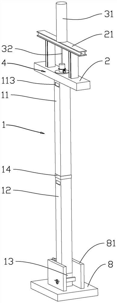
[0040] The embodiment of the present application discloses a method for butt joint installation of a rectangular steel column by first lifting the beam and then the column in a narrow space. refer to figure 1 , figure 2 , In a narrow space, the installation method of butt joint installation of rectangular steel columns includes the following construction steps:

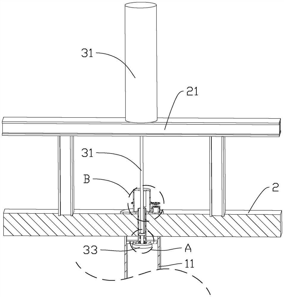
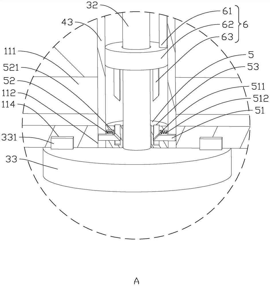
[0041] S1. Divide the steel column 1 into the first section column 11, the second section column 12 and the third section column 13, install the third section column 13 on the lower platform 8, and install the steel column at the end of the upper platform 2 A lifting bracket 21 is arranged on the beam, and a hydraulic lifter 3 and a control assembly 4 for adjusting the position of the first column 11 are installed on the lifting bracket 21. The upper platform 2 is provided with a communication hole 22, and the connection...


PUM


Abstract

The invention discloses a narrow space beam-column-first lifting rectangular steel stand column butt joint installation method which comprises the following construction steps that S1, a steel column is divided into a first section of column body, a second section of column body and a third section of column body, the third section of column body is installed on a lower layer platform, a hydraulic lifter and a control assembly are arranged on an upper layer platform, and the first section of column body and the second section of column body are in butt joint; a communicating hole is formed in the upper-layer platform; s2, stiffening plates are fixed to the upper ends of the first column body section and the second column body section, positioning openings are formed in the stiffening plates, and operation openings are formed in the outer side walls of the first column body section and the second column body section; s3, a hydraulic lifter is started, and the first section of column body is lifted to the position below the communicating hole and fixed; s4, the hydraulic lifter is started to lift the second section of the column body, the second section of the column body is fixedly connected with the third section of the column body, and a connecting section is reserved between the first section of the column body and the second section of the column body; and S5, connecting sections are installed and welded. The steel stand column has the effects that constructors can conveniently and vertically install the steel stand column, and the project progress is accelerated.

Description

technical field [0001] The present application relates to the field of butt joint installation of steel columns, in particular to a method for butt joint installation of rectangular steel columns in a narrow space where beams are lifted first and then columns are lifted. Background technique [0002] When construction personnel build subway stations, construction personnel often use steel columns as the support of the platform. The general construction steps are to use large-scale hoisting equipment such as cranes to hoist the steel columns to the upper surface of the existing platform, and then the operators vertically set the steel columns. The bottom of the column is fixedly installed with the existing platform, and then the operator pours the upper platform on the upper surface of the steel column. [0003] In view of the related technologies mentioned above, the inventor believes that when the planned subway station meets the completed subway station, the construction p...

Claims


Application Information

Patent Timeline
IPC IPC(8): E02D29/045E04C3/32E04G21/16
CPCE02D29/045E02D29/04E04C3/32E04G21/16
Inventor 郑玉明毛磊李宗文秦开文张怀忠邱亮杨大兵周松周雄曹洋洋张恒
Owner CHINA RAILWAY GUANGZHOU ENG GRP CO LTD
Learn More