Water resistance tension equipment for fitness exercise
A technology of tension and equipment, applied in gymnastics equipment, muscle training equipment, sports accessories, etc., can solve problems such as injuries, and achieve the effects of high safety, wide adaptability, and convenient use
- Summary
- Abstract
- Description
- Claims
- Application Information
AI Technical Summary
Problems solved by technology
Method used
Image
Examples
Embodiment 1
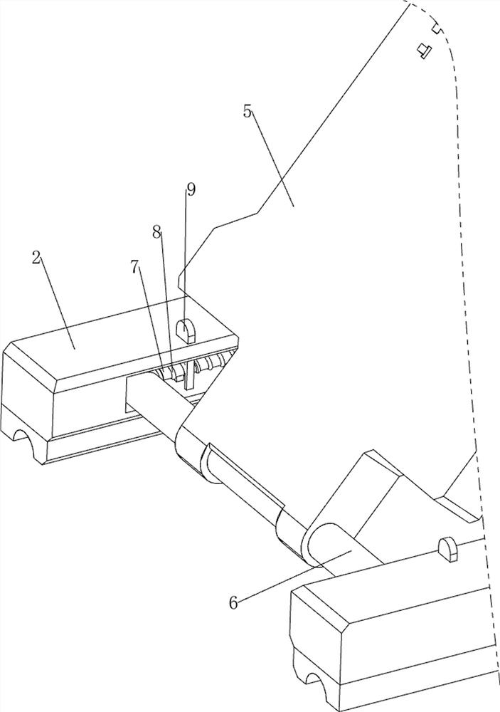
[0042] A water resistance pulling device for fitness exercises such as Figure 1-Figure 10 As shown, it includes a bottom plate 1, a first fixed plate 2, a first support plate 3, a first movable plate 4, a second movable plate 5, a first movable rod 6, a first limit rod 7, a first spring 8, The first buckle 9, the pull cord 91, the tension mechanism 10, the fixing mechanism 11 and the water storage mechanism 12; , the first support plate 3 is located on the right side of the first fixed plate 2, the first support plate 3 top is rotatably provided with a first movable plate 4, and the left side of the first movable plate 4 is rotatably provided with a second movable plate 5. The inner left part of the fixed plate 2 is provided with a first stop rod 7, and the first movable rod 6 is slidably arranged between the first limit rods 7, and the second movable plate 5 bottom is connected with the first movable rod 6 in a rotational manner. The first limit rod 7 is equipped with a fir...
Embodiment 2
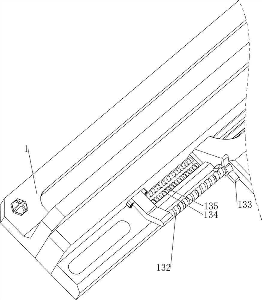
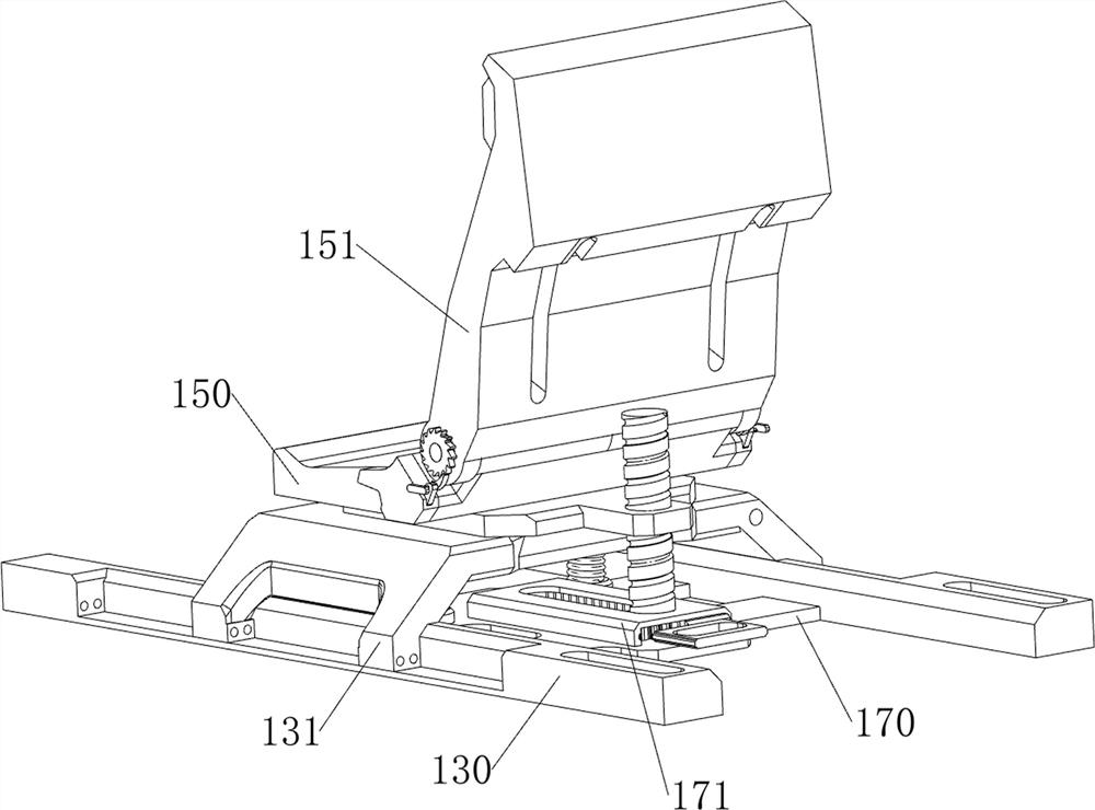
[0048] On the basis of Example 1, such as Figure 11-Figure 17 As shown, an adjustment mechanism 13 is also included, and the adjustment mechanism 13 includes a third fixed plate 130, a third movable plate 131, a first screw rod 132, a first torsion block 133, a third spring 134 and a third limit rod 135 , the top left side of the base plate 1 is provided with a third fixed plate 130 symmetrically front and rear, the middle part of the inner side of the third fixed plate 130 is provided with a first screw 132, and the left and right symmetrical threads of the first screw 132 are provided with a first torsion block 133 , the inner lower part of the third fixed plate 130 is provided with two third limit rods 135, the third movable plate 131 is slidably arranged between the third limit rods 135, and the third movable plate 131 cooperates with the first torsion block 133 The third spring 134 is sheathed symmetrically on the third limiting rod 135, and the two ends of the third spr...
Embodiment 3
[0054] On the basis of Example 2, such as Figure 18-Figure 21 As shown, a pressurizing mechanism 16 is also included. The pressurizing mechanism 16 includes a rotating wheel 160, a second screw mandrel 161 and a hexagonal column 162. The top of the second support plate 105 is provided with a rotating wheel 160, and the middle part of the rotating wheel 160 is provided with a second Two screw mandrels 161, the bottom of the second screw mandrel 161 is threadedly provided with a hexagonal prism 162, the first rotating shaft 108 and the second rotating shaft 123 are both slidably connected with the hexagonal prism 162, and the hexa prism 162 cooperates with the second rotating plate 125.
[0055] When people pull the stay cord 91 to the left, the stay cord 91 drives the first rotating shaft 108, the second rotating shaft 123 and the first rotating plate 124 to rotate, and the scroll spring 107 is deformed. Under the action of water resistance and water pressure, Reach the purpos...
PUM
 Abstract
Description
Claims
Application Information
 - R&D Engineer
- R&D Manager
- IP Professional
- Industry Leading Data Capabilities
- Powerful AI technology
- Patent DNA Extraction
Browse by: Latest US Patents, China's latest patents, Technical Efficacy Thesaurus, Application Domain, Technology Topic, Popular Technical Reports.
© 2024 PatSnap. All rights reserved.Legal|Privacy policy|Modern Slavery Act Transparency Statement|Sitemap|About US| Contact US: help@patsnap.com


