
Control device for smart power grid

A technology for control devices and smart grids, applied in the direction of measuring devices, substation/switch layout details, electrical components, etc., can solve problems such as high temperature in control cabinets, affecting normal operation of equipment, and timely distribution of temperature

Active Publication Date: 2022-03-04
海南电网有限责任公司
View PDF9 Cites 0 Cited by
  • Summary
  • Abstract
  • Description
  • Claims
  • Application Information

AI Technical Summary

Problems solved by technology

[0004] When the control cabinet is in normal use, the staff needs to check the temperature of the control cabinet on time to avoid failures caused by excessive temperature of the control cabinet, especially at the position of the wiring terminals inside the control cabinet. Faults such as excessive resistance are prone to occur at the connection position, which may cause the temperature of the control cabinet to be too high. Existing staff usually use the following two methods to detect the internal temperature of the control cabinet. First, add a temperature sensor inside the control cabinet, so that Monitor the temperature change in the cabinet. However, the temperature sensor monitors a large range. When the overheating between the terminal and the wire in a local area takes a while, the temperature can be transmitted to the sensor position in the control cabinet, and the temperature cannot be timely detected. The response and detection have hysteresis; second, wrap the wireless temperature sensor at the terminal and the wire of the control cabinet, and use the external terminal to monitor the temperature at the connection position between the terminal and the wire. During monitoring, the temperature may not be released in time, which will affect the normal operation of the equipment

Method used


Image

  • Control device for smart power grid
  • Control device for smart power grid
  • Control device for smart power grid

Examples


Embodiment Construction

[0031] The following will clearly and completely describe the technical solutions in the embodiments of the present invention with reference to the accompanying drawings in the embodiments of the present invention. Obviously, the described embodiments are only some, not all, embodiments of the present invention. Based on the embodiments of the present invention, all other embodiments obtained by persons of ordinary skill in the art without making creative efforts belong to the protection scope of the present invention.

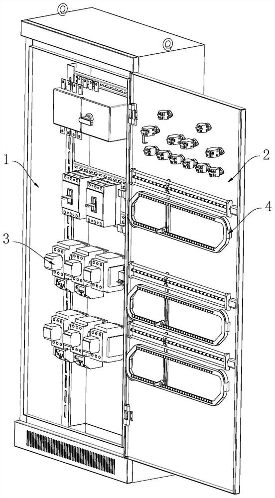
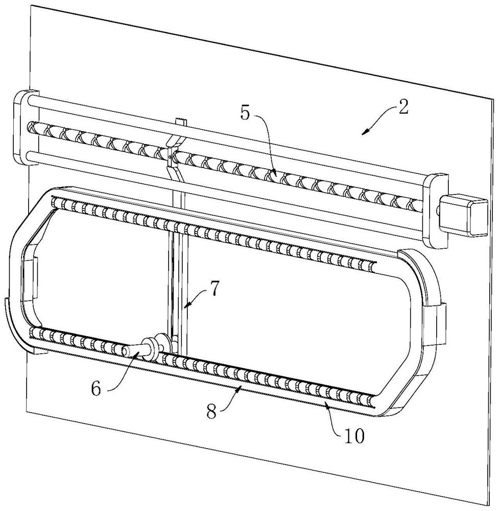
[0032] see Figure 1-9 , the present invention provides a technical solution: a control device for a smart grid, comprising:

[0033] A cabinet body 1, one side of the cabinet body 1 is provided with a cabinet door 2, and the cabinet door 2 is rotationally connected with respect to the cabinet body 1, and the inside of the cabinet body 1 is provided with a plurality of electronic components 3, and a plurality of electronic components 3 Installed on the track ...


PUM


Abstract

The invention discloses a control device for a smart power grid, and the device comprises a cabinet body, one side of the cabinet body is provided with a cabinet door, and the interior of the cabinet body is provided with a plurality of electronic components; the device comprises a cabinet door, a plurality of detection mechanisms, the plurality of detection mechanisms are installed on the cabinet door, the detection mechanisms can detect the connection position of an electronic component and a wire, each detection mechanism comprises a driving mechanism installed on the cabinet door, a rail is installed on the cabinet door, and the driving mechanisms are arranged on the cabinet door. On one hand, the detection piece is separated from the connection position of the terminal and the wire, heat dissipation of the connection position is not affected, normal use of equipment can be guaranteed, on the other hand, the detection piece is close to the connection position, the connection position of the terminal and the wire is detected circularly, the temperature conduction time is short, and the detection effect is good. And the temperature information can be quickly transmitted to the terminal, so that the temperature at the connection position can be conveniently fed back in time, and a maintainer can be reminded to maintain in time.

Description

technical field [0001] The invention relates to the technical field of smart grids, in particular to a control device for smart grids. Background technique [0002] The smart grid is the intelligence of the grid, also known as "grid 2.0", which is based on an integrated, high-speed two-way communication network, through advanced sensing and measurement technology, advanced equipment technology, advanced control methods and The application of advanced decision support system technology achieves the goals of reliability, security, economy, efficiency, environmental friendliness and safe use of the power grid. Its main features include self-healing, incentives and protection of users, resistance to attacks, and power quality that meets user needs , allowing the access of various forms of power generation, starting the power market and optimizing and efficient operation of assets. [0003] The control cabinet is the key control equipment in the smart grid. The control cabinet i...

Claims


Application Information

Patent Timeline
IPC IPC(8): H02B1/32H02B1/34H02B1/052G01K1/14G01K13/00
CPCH02B1/32H02B1/34H02B1/052G01K1/14G01K1/146G01K13/00
Inventor 王国仕王宁许家伟吉承文马超颜清刘瑛张应斌
Owner 海南电网有限责任公司
Learn More