Supporting mechanism and supporting method for cable tube
A support mechanism and support method technology, applied in the direction of electrical components, etc., can solve the problems that the cables of the support frame are easily entangled together, the support of the support is difficult to maintain stability, and different cables cannot be classified, so that it is not easy to loosen, strengthen the support, and facilitate classification effect
- Summary
- Abstract
- Description
- Claims
- Application Information
AI Technical Summary
Problems solved by technology
Method used
Image
Examples
specific Embodiment 1
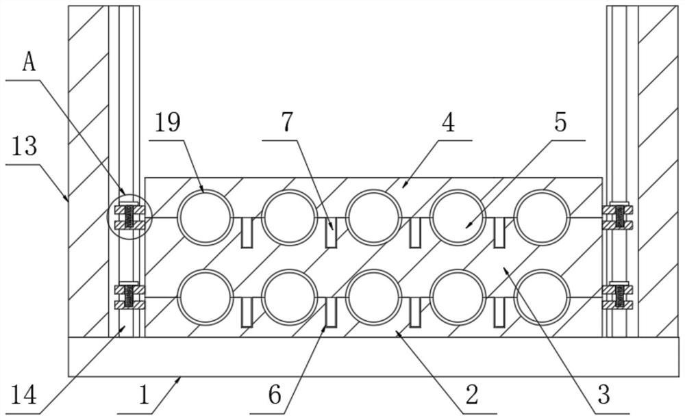
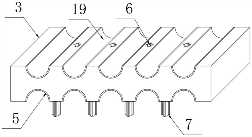
[0026] Such as figure 1 with image 3 As shown, including a support base plate 1, the upper surface of the support base plate 1 is fixedly connected with a first placement frame 2, a second placement frame 3 is arranged above the first placement frame 2, and a third placement frame is arranged above the second placement frame 3. Placing rack 4, the upper side surface of the first placing rack 2 and the upper and lower side surfaces of the second placing rack 3, and the lower side surface of the third placing rack 4 are all provided with a plurality of placing grooves 5, and the inner walls of a plurality of placing grooves 5 All are fixedly connected with cushions 19, and the upper side surface of the first placement frame 2 and the upper side surface of the second placement frame 3 are provided with a plurality of draw-in slots 6 away from the side of the placement groove 5, and the lower side of the second placement frame 3 The surface and the lower side surface of the thir...
specific Embodiment 2
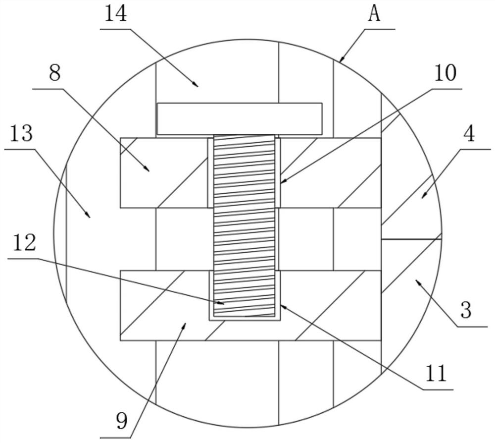
[0028] Such as figure 1 with figure 2 Shown, the lower side of the left and right side surfaces of the second placement frame 3 and the left and right side surfaces of the third placement frame 4 are all fixedly connected with upper connecting blocks 8, and the left and right sides surfaces of the first placement frame 2 are connected with the second placement frame. 3 The upper sides of the left and right sides are fixedly connected with lower connection blocks 9, the upper surfaces of multiple upper connection blocks 8 are provided with threaded holes 10, and the upper surfaces of multiple lower connection blocks 9 are provided with thread grooves 11 , the inner walls of a plurality of corresponding threaded holes 10 and the inner walls of the threaded grooves 11 are jointly threaded with screw columns 12, the connection between the plurality of placement racks is more stable, not easy to loosen, and it is limited.
specific Embodiment 3
[0030] Such as Figure 4 As shown, connecting rods 15 are fixedly connected to the front and rear sides of the left and right sides of the supporting base plate 1, and the opposite side surfaces of the corresponding two connecting rods 15 are fixedly connected to supporting rods 16. Roof 17, the lower surface of the roof 17 is fixedly connected with a plurality of mounting plates 18, and the opposite side surfaces of the plurality of mounting plates 18 are respectively fixedly connected with the opposite side surface of the connecting rod 15 and the opposite side surface of the connecting frame 13 , The triangular stability structure is used between the mounting frames, which makes the whole support mechanism more stable and not easy to loosen.
PUM
 Abstract
Description
Claims
Application Information
 - R&D
- Intellectual Property
- Life Sciences
- Materials
- Tech Scout
- Unparalleled Data Quality
- Higher Quality Content
- 60% Fewer Hallucinations
Browse by: Latest US Patents, China's latest patents, Technical Efficacy Thesaurus, Application Domain, Technology Topic, Popular Technical Reports.
© 2025 PatSnap. All rights reserved.Legal|Privacy policy|Modern Slavery Act Transparency Statement|Sitemap|About US| Contact US: help@patsnap.com


