V-shaped thrust rod support and V-shaped thrust rod connecting structure
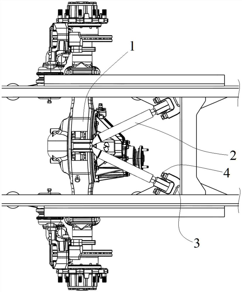
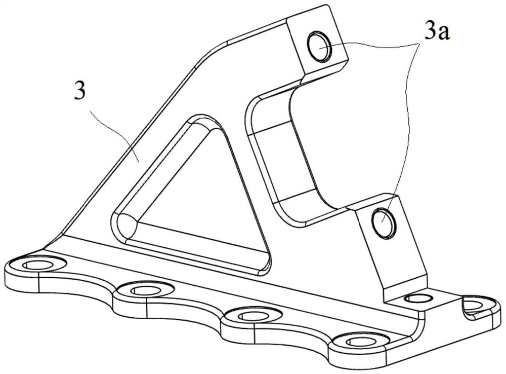
A technology of connecting structure and thrust rod, applied in the direction of cantilever mounted on the pivot, suspension, transportation and packaging, etc., can solve the problems of difficult assembly and easy loosening of the V-shaped thrust rod connection.
- Summary
- Abstract
- Description
- Claims
- Application Information
AI Technical Summary
Problems solved by technology
Method used
Image
Examples
Embodiment 1
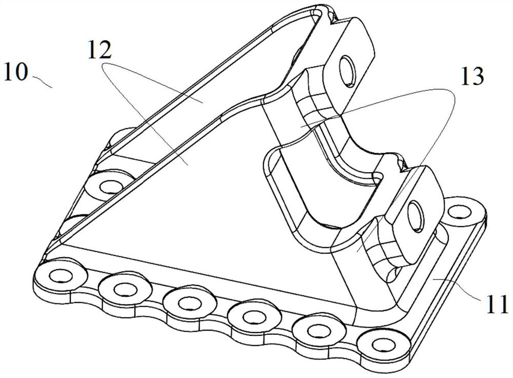
[0035] Such as image 3 with Figure 4 As shown, Embodiment 1 of the present application provides a V-shaped thrust rod support 10 , including a bottom plate 11 , a side plate 12 and a mounting portion 13 .
[0036] Wherein, the number of the side plates 12 is two, and the two side plates 12 are vertically connected to the bottom plate 11 and arranged opposite to each other at intervals.
[0037] The mounting portion 13 is connected between the two side plates 12 and located at one end of the side plate 12 , and two mounting holes for mounting a V-shaped thrust rod are penetrating through the mounting portion 13 .
[0038] Specifically, in this embodiment, the installation part 13 includes an upper installation part 131 and a lower installation part 132, the upper installation part 131 is connected to the upper parts of the two side plates 12, and the lower installation part 132 is connected to In the lower part of the two side plates 12, the two installation holes are respe...
Embodiment 2
[0047] Such as Figure 5 to Figure 7 and combine image 3 with Figure 4 As shown, Embodiment 2 of the present application discloses a V-shaped thrust rod connection structure using the above-mentioned Embodiment 1. Specifically, it includes a vehicle axle 20, a V-shaped thrust rod 30, and two frame longitudinal beams 40 (for convenience) Observe, one of which is not shown) and the above-mentioned V-shaped thrust rod support 10.
[0048] Wherein, the V-shaped thrust rod 30 includes a large-end ball joint 31 located at the apex, two ball joints 32 extending from the top to both sides to form a V shape, and corresponding ball joints 32 that pass through the ball joints 32. The small-end ball joint 33, when assembled, the apex big-end ball joint 31 is connected to the axle 20, and the two V-shaped thrust rod supports 10 are connected to the two correspondingly through the fastening holes 11a thereon. The frame longitudinal beam 40, the small-end spherical hinge 33 at the exten...
PUM
 Abstract
Description
Claims
Application Information
 - R&D
- Intellectual Property
- Life Sciences
- Materials
- Tech Scout
- Unparalleled Data Quality
- Higher Quality Content
- 60% Fewer Hallucinations
Browse by: Latest US Patents, China's latest patents, Technical Efficacy Thesaurus, Application Domain, Technology Topic, Popular Technical Reports.
© 2025 PatSnap. All rights reserved.Legal|Privacy policy|Modern Slavery Act Transparency Statement|Sitemap|About US| Contact US: help@patsnap.com


