Leg joint movement device for orthopedic rehabilitation

A technology of orthopedic rehabilitation and mobilizers, applied in passive exercise equipment, physical therapy, etc., can solve problems such as high exercise intensity, low safety, easy to lose force and fall, and achieve high safety effects

Pending Publication Date: 2022-03-01
龙泳
View PDF0 Cites 0 Cited by
  • Summary
  • Abstract
  • Description
  • Claims
  • Application Information

AI Technical Summary

Problems solved by technology

[0004] In order to overcome the shortcoming that the patient is easy to lose strength and fall when walking on the ground with the help of auxiliary tools, the safety is not high, and the exercise intensity is high, which will make the patient more tired. Leg Joint Mobilizer for Orthopedic Rehabilitation with Fatigue

Method used


Image

  • Leg joint movement device for orthopedic rehabilitation
  • Leg joint movement device for orthopedic rehabilitation
  • Leg joint movement device for orthopedic rehabilitation

Examples


Embodiment 1

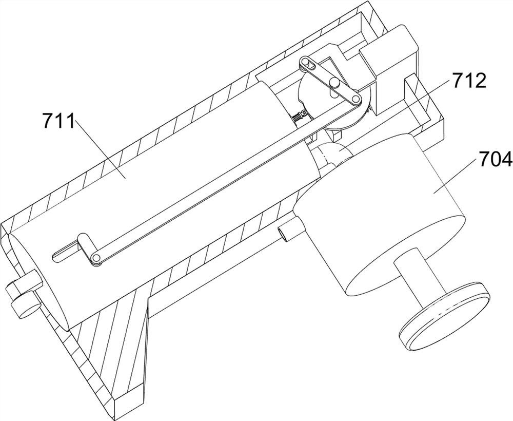
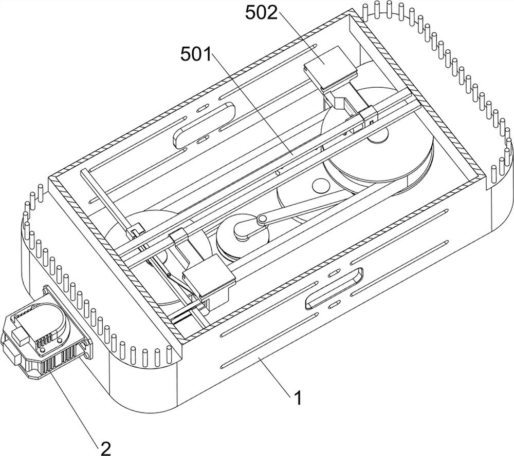
[0089] A leg joint mover for orthopedic rehabilitation, such as Figure 1-Figure 14 As shown, it includes a housing 1, a servo motor 2, a drive assembly 3, a rotating assembly 4, a moving assembly 5, a placement block 6, a disengagement assembly 7 and a reset assembly 8, a servo motor 2 is provided in the middle of the left side of the housing 1, and the housing The bottom of the body 1 is provided with a driving assembly 3, the inner bottom of the housing 1 is provided with a rotating assembly 4, the rotating assembly 4 is located outside the driving assembly 3, the rotating assembly 4 is provided with a moving assembly 5, and the moving assembly 5 is provided with a placement block 6, The moving component 5 is provided with a disengagement component 7 , and the moving component 5 is provided with a reset component 8 .

[0090] The driving assembly 3 includes a first transmission wheel 301, a first rotating shaft 302, a second transmission wheel 303, a first belt 304, an ecce...

Embodiment 2

[0097] On the basis of Example 1, such as Figure 7 , Figure 11 and Figure 15 As shown, a connecting assembly 9 is also included, and the connecting assembly 9 includes a movable block 901, an eighth spring 902, a clamping block 903 and a ninth spring 904, and a movable block 901 is slidingly provided on the inner side of the slider 502 on the rear side, The upper part of the rear side of the movable block 901 is rotationally connected with the right side of the second rotating rod 802, and the eighth spring 902 is arranged between the lower part of the rear side of the movable block 901 and the slider 502 on the rear side, and the inner rear part of the slider 502 on the front side slides The formula is provided with a clamping block 903, and the clamping block 903 cooperates with the movable block 901, and two ninth springs 904 are arranged between the front side of the clamping block 903 and the sliding block 502 on the front side.

[0098] When the slide block 502 on t...


PUM


Abstract

The invention relates to a joint movement device, in particular to a leg joint movement device for orthopedic rehabilitation. The leg joint movement device for rehabilitation in the orthopedics department is high in safety and capable of reducing the fatigue feeling of a patient. The leg joint movement device for orthopedic rehabilitation comprises a shell and a servo motor, and the servo motor is arranged in the middle of one side of the shell; the driving assembly is arranged at the bottom in the shell; the rotating assembly is arranged at the bottom in the shell, and the rotating assembly is located on the outer side of the driving assembly; and the moving assembly is arranged on the rotating assembly. Through cooperation of the driving assembly, the rotating assembly, the moving assembly, the placing block, the separating assembly and the resetting assembly, when the patient sits, the feet of the patient can be automatically driven to move left and right in a staggered and reciprocating mode, so that leg joints of the patient move, the rehabilitation effect is achieved, and safety is high.

Description

technical field [0001] The invention relates to a joint mover, in particular to a leg joint mover for orthopedic rehabilitation. Background technique [0002] Orthopedic patients need to do some proper rehabilitation training after surgery, so as to further treat the disease, so as to prevent dysfunction and promote functional recovery, so as to restore the function of the motor system. [0003] When patients do rehabilitation training, they usually walk on the ground with the help of some auxiliary tools, or move their legs by themselves, but such exercise intensity is high, which will make the patient more tired and the rehabilitation effect is not good. During the walking process, the patient did not get a timely rest, easily lost strength and fell down, aggravated the condition, and the safety was not high. Therefore, a leg joint mobilizer for orthopedic rehabilitation with high safety and able to reduce the fatigue of the patient was designed. . Contents of the inven...

Claims


Application Information

Patent Timeline
Patent Type & Authority Applications(China)
IPC IPC(8): A61H1/02
CPCA61H1/0262A61H2201/5056
Inventor 龙泳
Owner 龙泳
Why Eureka
Try Eureka