Locomotive side bearing finite element analogue simulation method and simulation model
A simulation method and finite element technology, applied in the field of locomotive side bearing finite element simulation simulation method and simulation model, can solve the problems of inconvenient moment transmission, inconvenient accurate calculation of side bearing contact position stress, complicated setting, etc.
- Summary
- Abstract
- Description
- Claims
- Application Information
AI Technical Summary
Problems solved by technology
Method used
Image
Examples
Embodiment 1
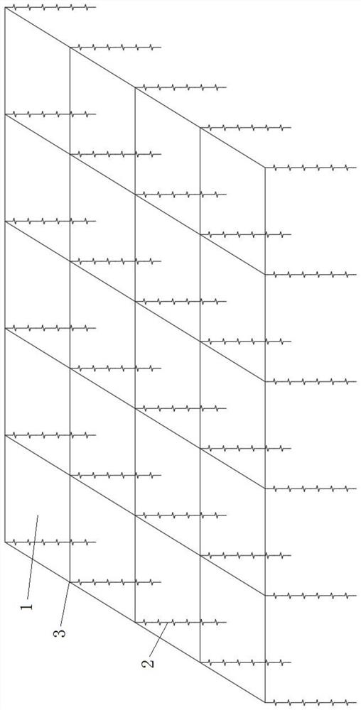
[0022] Such as figure 1 As shown, a finite element simulation method for side bearing of a locomotive, the side bearing contact surface is discretized into multiple side bearing contact surface finite element units 1 through finite element simulation, and the rubber side bearing is discretized into multiple spring finite element units through finite element simulation The element element 2, each finite element element node 3 between the plurality of side bearing contact surface finite element elements 1 is connected to a single spring finite element element 2.
[0023] The invention is convenient for accurate calculation of the stress near the contact position of the side bearing, convenient for moment transmission, and simple setting.
[0024] As a preferred technical solution, it is assumed that the side bearing material is uniform.
[0025] This further improves the simulation accuracy.
[0026] As a preferred technical solution, it is assumed that the stiffness of each s...
Embodiment 2
[0039] Such as figure 1 As shown, as a further optimization of Embodiment 1, this embodiment includes all the technical features of Embodiment 1. In addition, this embodiment also includes the following technical features:
[0040] A finite element simulation model of a side bearing of a locomotive, formed according to the finite element simulation method for a side bearing of a locomotive, comprising a plurality of side bearing contact surface finite element units 1, a plurality of spring finite element units 2, a plurality of Each finite element element node 3 between the side bearing contact surface finite element elements 1 is connected to a single spring finite element element 2 .
[0041] The invention is convenient for accurate calculation of the stress near the contact position of the side bearing, convenient for moment transmission, and simple setting.
Embodiment 3
[0043] Such as figure 1 As shown, this embodiment includes all the technical features of Embodiment 1 and Embodiment 2. On the basis of Embodiment 1 and Embodiment 2, this embodiment provides a more detailed implementation mode.
[0044] The side bearing contact surface of the locomotive body is an area, which is not a rigid surface, but an elastic surface. It is required that each node 3 of the discrete finite element element has relatively independent displacement and reaction force. In order to maintain this characteristic, the side bearing must also be discretized to ensure that each unit node in the contact surface area is supported by a spring finite element unit 2. Assuming that the material of the side bearing is uniform, the stiffness of each spring finite element unit 2 is the same. Each spring finite element unit 2 is connected in parallel to form the whole side bearing, and the stiffness of a single spring finite element unit 2 is k=K / n, where K is the stiffness of...
PUM
 Abstract
Description
Claims
Application Information
 - R&D
- Intellectual Property
- Life Sciences
- Materials
- Tech Scout
- Unparalleled Data Quality
- Higher Quality Content
- 60% Fewer Hallucinations
Browse by: Latest US Patents, China's latest patents, Technical Efficacy Thesaurus, Application Domain, Technology Topic, Popular Technical Reports.
© 2025 PatSnap. All rights reserved.Legal|Privacy policy|Modern Slavery Act Transparency Statement|Sitemap|About US| Contact US: help@patsnap.com

