
Gas-liquid-solid three-phase fire extinguishing method and device

A fire extinguishing device and gas-liquid-solid technology, applied in the field of fire extinguishing, can solve the problems of reduced jet velocity, easy re-ignition, and limited coverage of the fire area, and achieve the effect of increased cooling speed and good fire extinguishing effect

Pending Publication Date: 2022-02-11
西安安备特安防科技有限公司
View PDF0 Cites 0 Cited by
  • Summary
  • Abstract
  • Description
  • Claims
  • Application Information

AI Technical Summary

Problems solved by technology

The above technologies are widely used in the prevention and control of fire accidents due to their excellent fire extinguishing performance, but their shortcomings are also obvious
Inert gas fire extinguishing technology In the process of jet flow, pure gas entrains a large amount of air, resulting in a rapid decrease in jet velocity, which limits the coverage of the fire area, and the heat transfer coefficient between gas and solid is usually small, so the cooling effect on Class A fires is limited. prone to re-ignition
Foam fire extinguishing is an essential fire-fighting facility in chemical plants, gas stations and other places. This technology covers the fire area with foam to isolate oxygen to achieve the purpose of fire control. However, it is difficult to clean up the on-site residue after the fire is extinguished, so it cannot be applied to libraries, Computer rooms, museums, laboratories and other places of great value

Method used


Image

  • Gas-liquid-solid three-phase fire extinguishing method and device
  • Gas-liquid-solid three-phase fire extinguishing method and device
  • Gas-liquid-solid three-phase fire extinguishing method and device

Examples


Embodiment Construction

[0021] In order to make the objects and advantages of the present invention clearer, the present invention will be further described in detail below in conjunction with the examples. It should be understood that the specific embodiments described herein are only used to explain the present invention, but not to limit the present invention.

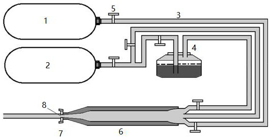
[0022] like figure 2 As shown, the embodiment of the present invention provides a gas-liquid-solid three-phase fire extinguishing device, including a gas source, a mixture preparation chamber, an outlet system and a low-temperature resistant pipeline, and the gas source is composed of CO 2 Dewar 1 and N 2 Composition of Dewar 2; CO 2 The Dewar tank 1 communicates with the mixture preparation chamber through the low-temperature-resistant pipeline 3 equipped with a flow regulating valve 5, N 2 The Dewar tank 2 is respectively connected to the nuclear agent atomizer 4 and the mixture preparation channel 6 through the low temperature resis...


PUM


Abstract

The invention relates to the technical field of fire extinguishing, and in particular, relates to a gas-liquid-solid three-phase fire extinguishing device which comprises a gas source, a mixture preparation cavity channel, an outlet system and low-temperature-resistant pipelines; the gas source is composed of a CO2 Dewar tank and an N2 Dewar tank; the CO2 Dewar tank is communicated with the mixture preparation cavity channel through the low-temperature-resistant pipeline provided with a flow regulating valve; the N2 Dewar tank is respectively communicated with a nucleating agent atomizer and the mixture preparation cavity channel through the low-temperature-resistant pipeline provided with a flow regulating valve, and the low-temperature-resistant pipeline provided with a flow regulating valve is arranged between the nucleating agent atomizer and the mixture preparation cavity channel; and the outlet system is composed of a throat, an anti-blocking supercharger and an outlet, and the anti-blocking supercharger and the throat are used for pressurizing the mixture preparation cavity. Three-phase mixture formed by CO2 gas, liquid nitrogen and dry ice particles is used for extinguishing fire, the cooling speed is increased by several times and even dozens of times, and the fire extinguishing effect is good.

Description

technical field [0001] The invention relates to the technical field of fire extinguishing, in particular to a gas-liquid-solid three-phase fire extinguishing method and device. Background technique [0002] Fire is one of the most common and frequent types of disasters in various accidents. Once there is no control and prevention, it will easily pose a huge threat to the safety of people's lives and properties. Traditional fire extinguishing technologies include: inert gas fire extinguishing technology, dry powder fire extinguishing technology, foam fire extinguishing technology, etc. The above technologies are widely used in the prevention and control of fire accidents due to their excellent fire extinguishing performance, but their shortcomings are also obvious. Inert gas fire extinguishing technology In the process of jet flow, pure gas entrains a large amount of air, resulting in a rapid decrease in jet velocity, limited coverage of the fire area, and the heat transfer ...

Claims


Application Information

Patent Timeline
Patent Type & Authority Applications(China)
IPC IPC(8): A62C5/00A62C31/02
CPCA62C5/004A62C31/02
Inventor 张辛亥郑仲明张首石冯浩赵思琛王凯
Owner 西安安备特安防科技有限公司
Learn More