
Camera stability control system and method

A stable control method and technology, applied in control systems, cameras, propulsion systems, etc., can solve the problems that the control accuracy cannot meet the needs of users and need to be improved, and can offset offset, reduce the size of the magnetic mechanism, and achieve high sensitivity. Effect

Active Publication Date: 2022-01-28
微传智能科技(常州)有限公司
View PDF3 Cites 0 Cited by
  • Summary
  • Abstract
  • Description
  • Claims
  • Application Information

AI Technical Summary

Problems solved by technology

However, the control accuracy of the existing camera stabilization system can no longer meet the needs of users and needs to be improved

Method used


Image

  • Camera stability control system and method
  • Camera stability control system and method
  • Camera stability control system and method

Examples


Embodiment 1

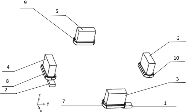
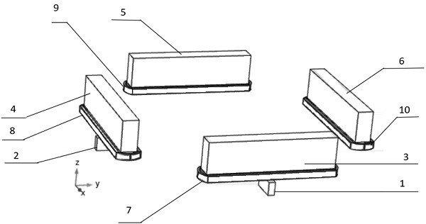
[0071] In Embodiment 1, the received signal of the AMR sensor is the magnetic field angle signal of Bx and By, and the signal curve is obtained as Figure 6 as shown, Figure 6 The fitting function of three straight lines-the relationship between the magnetic field angle y and the moving distance x is listed in ; in the existing implementation, the received signal of the HALL sensor is Bz perpendicular to the XY plane (such as figure 1 Shown) the magnetic field strength, the signal curve is obtained as Figure 5 shown. Figure 5 The fitting function of three straight lines - the relationship between the magnetic field strength y and the moving distance x is listed in . R2 in the two figures represents the degree of linearity of the straight line, the closer to 1, the better the linearity.

[0072] Although from the curve itself, the linearity is very good, but after accurate calculation, the linearity and cross influence of the two can be obtained as shown in Table 1 below....


PUM


Abstract

The invention discloses a camera stability control system and method, and belongs to the technical field of camera control. The camera stability control system comprises a controller, a first AMR sensor, a second AMR sensor, a first group of magnetic mechanisms, a second group of magnetic mechanisms, at least one first coil and at least one second coil; the first group of magnetic mechanisms comprises at least one first magnetic mechanism, wherein each first magnetic mechanism is provided with the first coil; the second group of magnetic mechanisms comprises at least one second magnetic mechanism, wherein each second magnetic mechanism is provided with the second coil; the first group of magnetic mechanisms are arranged at a first position and are used for generating magnetic field signals; the second group of magnetic mechanisms are arranged at a second position and used for generating magnetic field signals; and the controller is connected with the AMR sensor and the coils, and adjusts current flowing through the corresponding coils according to magnetic field signals sensed by the AMR sensor so as to control the movement of the magnetic mechanisms. According to the camera stability control system and method, the movement of a lens in the horizontal direction can be adjusted, and the position of the lens is accurately controlled.

Description

technical field [0001] The invention belongs to the technical field of camera control, and relates to a camera control system, in particular to a camera stabilization control system. Background technique [0002] Optical Image Stabilization (OIS-Optical Image Stabilizer) is an effective solution in camera stabilization system to solve the image quality problem, with the rapid development of consumer electronics, consumers demand higher resolution optical zoom cameras , packed into smaller, lighter DSCs and handsets, blurring due to hand shake will become more noticeable, and stabilization systems will become standard features. [0003] How to solve hand shake has become an important indicator for evaluating camera stabilization systems. Blur from hand shake can be reduced by stabilizing the camera. A microcontroller sends a hand-shake signal to a small linear motor that moves the image sensor, compensating for the camera's motion. [0004] In order for the OIS system to w...

Claims


Application Information

Patent Timeline
Patent Type & Authority Applications(China)
IPC IPC(8): H02K41/035H02K11/215H02K11/30H02P7/025H02P5/46G03B5/00
CPCH02K41/0356H02K11/215H02K11/30H02P7/025H02P5/46G03B5/00
Inventor 许英华沙玉新
Owner 微传智能科技(常州)有限公司
Learn More