
Head-mounted display equipment, glasses leg component, glasses frame component and control method thereof

A head-mounted display and component technology, applied in glasses/goggles, optical components, non-optical accessories, etc., can solve problems such as large impact, affecting signal transmission quality, and damage to flexible circuit boards, so as to avoid signal attenuation and improve The effect of reliability and service life

Pending Publication Date: 2022-01-28
GEER TECH CO LTD
View PDF4 Cites 0 Cited by
  • Summary
  • Abstract
  • Description
  • Claims
  • Application Information

AI Technical Summary

Problems solved by technology

[0003] In the prior art, the signal transmission between the temple part and the main body of the device (i.e. the frame part) in the head-mounted display device is usually designed by using a flexible circuit board (FPC), but the bending times of the flexible circuit board are limited. The limitations of the flexible circuit board will cause irreversible damage after repeated bending, which will affect the quality of signal transmission. The greater the number of signal lines, the greater the impact; The system is turned on and off by means of buttons or touch switches, which causes inconvenience to use and poor user experience

Method used


Image

  • Head-mounted display equipment, glasses leg component, glasses frame component and control method thereof
  • Head-mounted display equipment, glasses leg component, glasses frame component and control method thereof
  • Head-mounted display equipment, glasses leg component, glasses frame component and control method thereof

Examples


Embodiment Construction

[0043] In order to make the purpose, technical solutions and advantages of the embodiments of the present invention clearer, the technical solutions in the embodiments of the present invention will be clearly and completely described below in conjunction with the drawings in the embodiments of the present invention. Obviously, the described embodiments It is a part of embodiments of the present invention, but not all embodiments. Based on the embodiments of the present invention, all other embodiments obtained by persons of ordinary skill in the art without making creative efforts belong to the protection scope of the present invention.

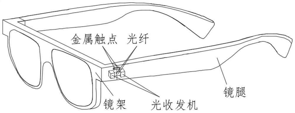
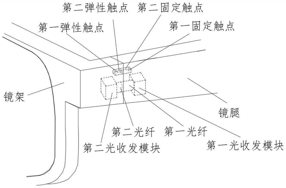
[0044] An embodiment of the present invention provides a temple part of a head-mounted display device. For details, please refer to figure 1 , figure 1 A schematic structural diagram of a head-mounted display device provided by an embodiment of the present invention; the temple parts may include: a motherboard module 11, a codec module 12, a...


PUM


Abstract

The invention discloses a glasses leg component, a glasses frame component, a control method and a control device of head-mounted display equipment and the head-mounted display equipment. The glasses leg component comprises a mainboard module, a coding and decoding module, a first optical transceiver module, a first optical fiber, a first power supply module and a first power supply contact. According to the invention, data transmission between the glasses leg component and the glasses frame component in the head-mounted display equipment is realized by adopting an optical fiber technology, and electric energy transmission between the glasses leg component and the glasses frame component is realized by adopting a contact power supply mode, so that signal attenuation caused by bending of an FPC or other wires is avoided, the reliability of the head-mounted display equipment is improved, and the service life of the head-mounted display equipment is prolonged so as to determine the use condition of the head-mounted display equipment by detecting power supply of the contacts, achieve automatic startup and shutdown of the head-mounted display equipment and improve user experience; and the glasses leg component and the glasses frame component can be assembled together after being assembled in a split manner, so that the assembly is more convenient, and the production yield of products is improved.

Description

technical field [0001] The present invention relates to the technical field of head-mounted display devices, and in particular to a temple part, a frame part, a control method, a control device, and a head-mounted display device of a head-mounted display device. Background technique [0002] At present, there are mainly two ways of designing the temples of the mainstream head-mounted display devices in the market. One is a strap design, and the temples do not need to be bent; the other is similar to ordinary glasses, and the temples can be bent. [0003] In the prior art, the signal transmission between the temple part and the main body of the device (i.e. the frame part) in the head-mounted display device is usually designed by using a flexible circuit board (FPC), but the bending times of the flexible circuit board are limited. The limitations of the flexible circuit board will cause irreversible damage after repeated bending, which will affect the quality of signal transm...

Claims


Application Information

Patent Timeline
Patent Type & Authority Applications(China)
IPC IPC(8): G02B27/01G02C11/00H04B10/40
CPCG02B27/017G02C11/10H04B10/40
Inventor 韩文强
Owner GEER TECH CO LTD
Learn More