
Reservoir monitoring device based on solar energy

A technology for monitoring devices and solar energy, applied in the direction of measuring devices, rainfall/precipitation gauges, photovoltaic modules, etc., can solve the problems of increasing the use of monitoring devices, increasing the use cost, and easy damage of solar panels, so as to increase the use and improve The effect of service life and energy consumption reduction

Pending Publication Date: 2022-01-25
HUANGHUAI UNIV
View PDF24 Cites 3 Cited by
  • Summary
  • Abstract
  • Description
  • Claims
  • Application Information

AI Technical Summary

Problems solved by technology

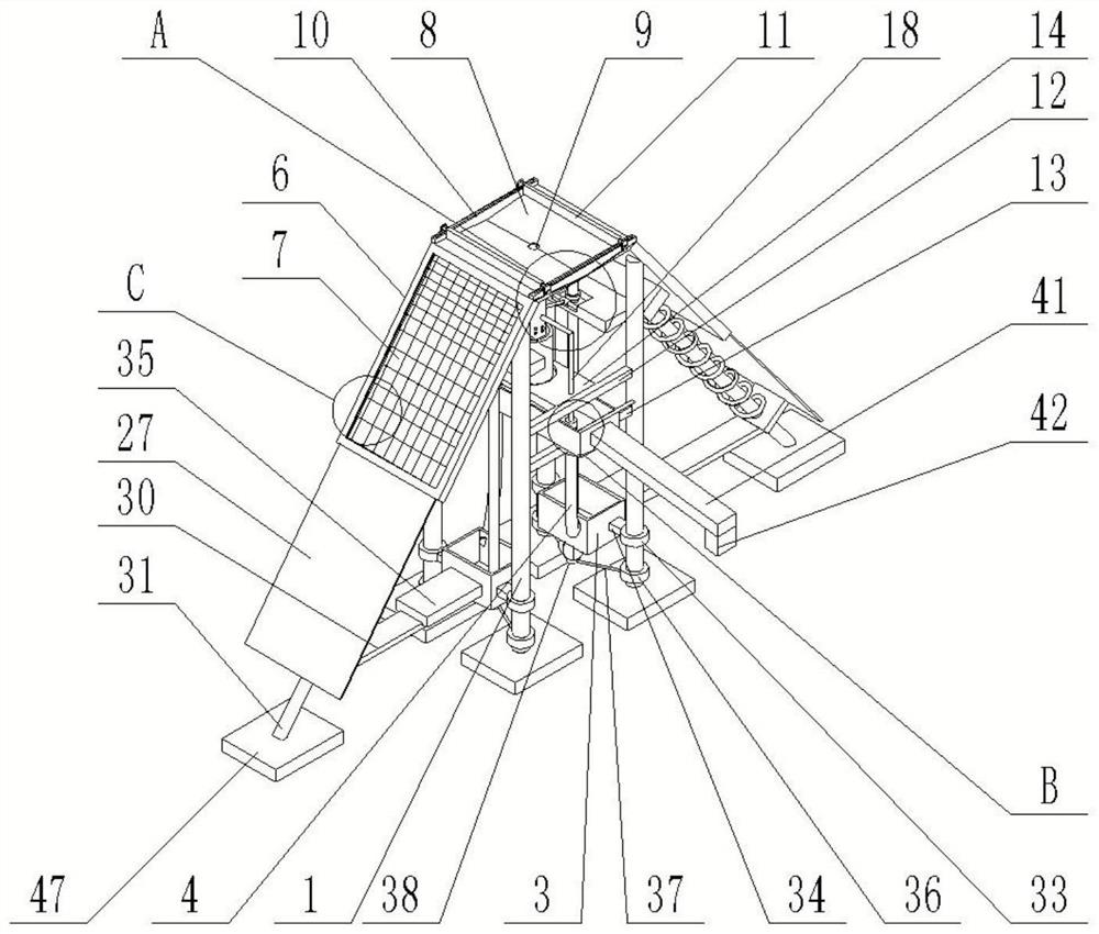
[0003] There are a variety of water level monitoring devices in the prior art. In order to reduce labor costs, most of the water level monitoring devices do not require manual operation. Solar panels are installed to absorb solar energy to generate electricity for the electronic devices in the monitoring device. However, due to outdoor weather The reason is that when it rains outdoors, the solar panel is exposed to the harsh external environment, which causes the solar panel to be easily damaged and increases the cost of use
[0004] In addition, the water level monitoring devices in the prior art rarely have the function of synchronously monitoring rainfall, so a reservoir monitoring device based on solar energy is provided to protect the solar panels when it rains outdoors, and at the same time monitor the rainfall, thereby increasing Use of the monitoring device

Method used


Image

  • Reservoir monitoring device based on solar energy
  • Reservoir monitoring device based on solar energy
  • Reservoir monitoring device based on solar energy

Examples


Embodiment Construction

[0033] The following will clearly and completely describe the technical solutions in the embodiments of the present invention with reference to the accompanying drawings in the embodiments of the present invention. Obviously, the described embodiments are only some, not all, embodiments of the present invention. Based on the embodiments of the present invention, all other embodiments obtained by persons of ordinary skill in the art without making creative efforts belong to the protection scope of the present invention.

[0034] In order to make the above objects, features and advantages of the present invention more comprehensible, the present invention will be further described in detail below in conjunction with the accompanying drawings and specific embodiments.

[0035]The invention provides a reservoir monitoring device based on solar energy, which includes a power supply part. A rainwater collector is fixedly connected to the top of the power supply part. A rainwater stor...


PUM


Abstract

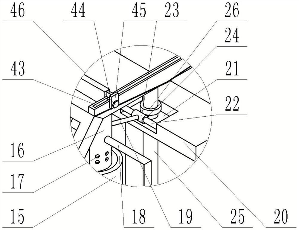
The invention discloses a reservoir monitoring device based on solar energy, which comprises a power supply part, a rainwater collection part is fixedly connected to the top end of the power supply part, a rainwater storage part is arranged below the rainwater collection part, the rainwater collection part and the rainwater storage part are correspondingly arranged, and a shielding part is arranged on one side, far away from the rainwater storage part, of the power supply part; the side, close to the rainwater storage part, of the power supply part is fixedly connected with supporting legs, a backflow box is arranged below the rainwater storage part, a gravity box is arranged below the backflow box, the backflow box communicates with the gravity box through a hose, the rainwater storage part and the backflow box are both fixedly connected with the supporting legs, and the gravity box is slidably connected with the supporting legs. According to the invention, the solar panel can absorb solar energy and convert the solar energy into electric energy to be stored so as to be used by a monitored electronic device when there is no rainfall, and the solar panel can be protected and the rainfall can be monitored when there is rainfall, so that the service life of the solar panel is prolonged, and the use purposes of the monitoring device are increased.

Description

technical field [0001] The invention relates to the technical field of reservoir monitoring, in particular to a reservoir monitoring device based on solar energy. Background technique [0002] Reservoir water level generally refers to the characteristic water level of the reservoir. In order to complete different tasks in different periods and under various hydrological conditions, the various reservoir water levels that need to be controlled to reach or allow to ebb are called the characteristic water level of the reservoir, which requires real-time monitoring of the reservoir water level , in order to achieve timely control of reservoir water level changes and prevent floods from occurring. [0003] There are a variety of water level monitoring devices in the prior art. In order to reduce labor costs, most of the water level monitoring devices do not require manual operation. Solar panels are installed to absorb solar energy to generate electricity for the electronic devic...

Claims


Application Information

Patent Timeline
Patent Type & Authority Applications(China)
IPC IPC(8): G01W1/14H02S40/00
CPCG01W1/14H02S40/00Y02E10/50Y02A90/10
Inventor 刘文富郭晓雷雷华宇杜文谢超刘丹杨华瑞
Owner HUANGHUAI UNIV
Learn More