
In-band scattering reduction structure based on four-dimensional antenna array and control method of in-band scattering reduction structure

A control method and antenna array technology, which are applied to antenna arrays, antennas, specific array feeding systems, etc., can solve the problems of antenna RCS, reduction and other problems that have not yet occurred, and achieve the effect of easy design and implementation and simple structure.

Inactive Publication Date: 2022-01-21
UNIV OF ELECTRONICS SCI & TECH OF CHINA
View PDF11 Cites 2 Cited by
  • Summary
  • Abstract
  • Description
  • Claims
  • Application Information

AI Technical Summary

Benefits of technology

This technology proposes a way for reducing interference from signals transmitted over wireless communication networks (WCNs). It achieves this by utilizing multiple antennas with different polarizations arranged around each other or placed next together within one another's space. By doing these techniques, it allows for more efficient signal transmission without affecting any others nearby devices.

Problems solved by technology

This patented describes various techniques related to suppressing interference caused by wireless signals transmitted between devices called targets. These include radars and communications systems, where they work together to improve their overall functionality. One technique involves applying specific types of antennas to enhance signal reception while minimizing unwanted reflections. Another approach proposes modifying the structure parameters of these antennas during manufacturing processes to increase their ability to prevent interferion effects.

Method used


Image

  • In-band scattering reduction structure based on four-dimensional antenna array and control method of in-band scattering reduction structure
  • In-band scattering reduction structure based on four-dimensional antenna array and control method of in-band scattering reduction structure
  • In-band scattering reduction structure based on four-dimensional antenna array and control method of in-band scattering reduction structure

Examples


Embodiment 1

[0067] Example 1: Dual-station RCS control with vertical incidence of 1×16 tapered slot antenna array

[0068] Specifically, considering the center frequency of the tapered slot antenna at 10 GHz and the corresponding free-space half-wavelength of the array element spacing of 10 GHz, when the in-band co-polarized incident wave is irradiated on the array antenna along the direction θ=0°, the optimal control is based on two The station angle [-30°, 30°] is the total RCS of the array antenna in the main threat angle domain. The final optimized coaxial line length is 10 mm, and the broadband load is 100 ohms. The time series of each unit is as Figure 4 shown. Figure 5 It shows the scattering pattern of the center frequency and the first three sidebands of the four-dimensional antenna array, indicating that time modulation can transfer part of the scattered energy of the center frequency to the sidebands, realizing the joint control of the space domain and the frequency domain ...

Embodiment 2

[0069] Example 2: Oblique-incidence single-station RCS control of 1×16 tapered slot antenna array

[0070] Specifically, consider the RCS optimization problem of the array antenna with the single station angle [-10°, 10°] as the threat angle domain when the in-band co-polarized incident wave irradiates the array antenna obliquely along the yoz plane at a center frequency of 10 GHz. The coaxial line length and broadband loading are the same as in Example 1. The final optimized time series of each unit is as follows: Figure 7 shown. Figure 8 It shows the scattering pattern of the center frequency and the first three sidebands of the four-dimensional antenna array, indicating that time modulation can transfer part of the scattered energy of the center frequency to the sidebands, realizing the joint control of the space domain and the frequency domain of the RCS. Figure 9Displays the single-station RCS comparison between the four-dimensional antenna array and two reference ar...


PUM


Abstract

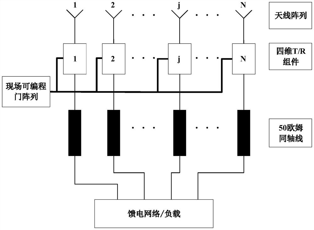
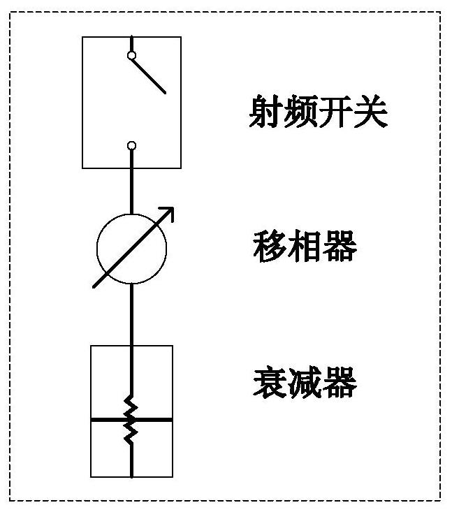
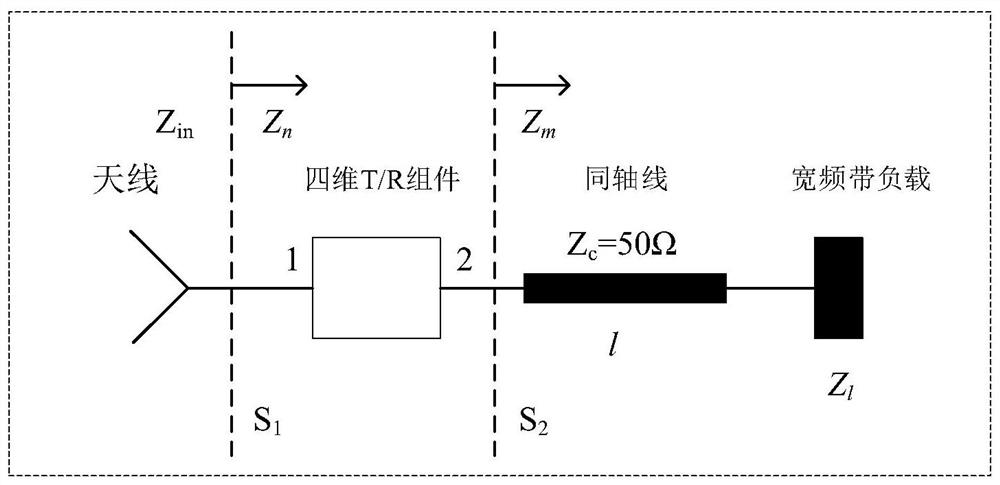
The invention belongs to the technical field of antenna engineering, and discloses an in-band scattering reduction structure based on a four-dimensional antenna array and a control method of the in-band scattering reduction structure . The rear end of each unit port of an antenna is sequentially connected with a four-dimensional T/R assembly, a coaxial line with the characteristic impedance of 50 ohms and a broadband load, wherein the four-dimensional T/R assembly comprises a radio frequency switch, a phase shifter and an attenuator. By optimizing the time sequence of the switch connected with each unit, the mode item scattering of the antenna is dynamically regulated and controlled, so that the total scattering field of the antenna is periodically changed, and the total scattering field of the array is estimated by using a method of unit RCS * array scattering array factors. According to the Fourier series theory, the RCS of the center frequency is partially transferred to a sideband, so that in-band RCS reduction is realized. According to the invention, the time-dimensional degree of freedom of the four-dimensional antenna array is fully utilized, so that the RCS of the antenna is jointly distributed in a space domain and a frequency domain, and compared with a traditional phased array, the phased array has a remarkable RCS reduction effect.

Description


Claims


Application Information

Patent Timeline
Owner UNIV OF ELECTRONICS SCI & TECH OF CHINA
Learn More