A high-speed drive motor shaft for new energy vehicles

A technology of new energy vehicles and high-speed motors, applied in the direction of motors, electric vehicles, brake actuators, etc., can solve problems such as the influence of heat and centrifugal force bearings, achieve the effects of reducing impact force, preventing jamming, and reducing negative effects

Inactive Publication Date: 2022-06-03
HANGZHOU SAIQI MACHINERY CO LTD
View PDF6 Cites 0 Cited by
  • Summary
  • Abstract
  • Description
  • Claims
  • Application Information

AI Technical Summary

Problems solved by technology

[0004] Based on this, it is necessary to address the above problems and propose a high-speed drive motor shaft for new energy vehicles that can fully and effectively dissipate heat according to the rotational speed, overcome the negative effects of centrifugal force, and ensure high-speed rotation, so as to solve the above-mentioned problems in the background technology. There is a problem that high-speed rotation will generate a lot of heat and centrifugal force will negatively affect the bearing in the technology

Method used


Image

  • A high-speed drive motor shaft for new energy vehicles
  • A high-speed drive motor shaft for new energy vehicles
  • A high-speed drive motor shaft for new energy vehicles

Examples


Embodiment 1

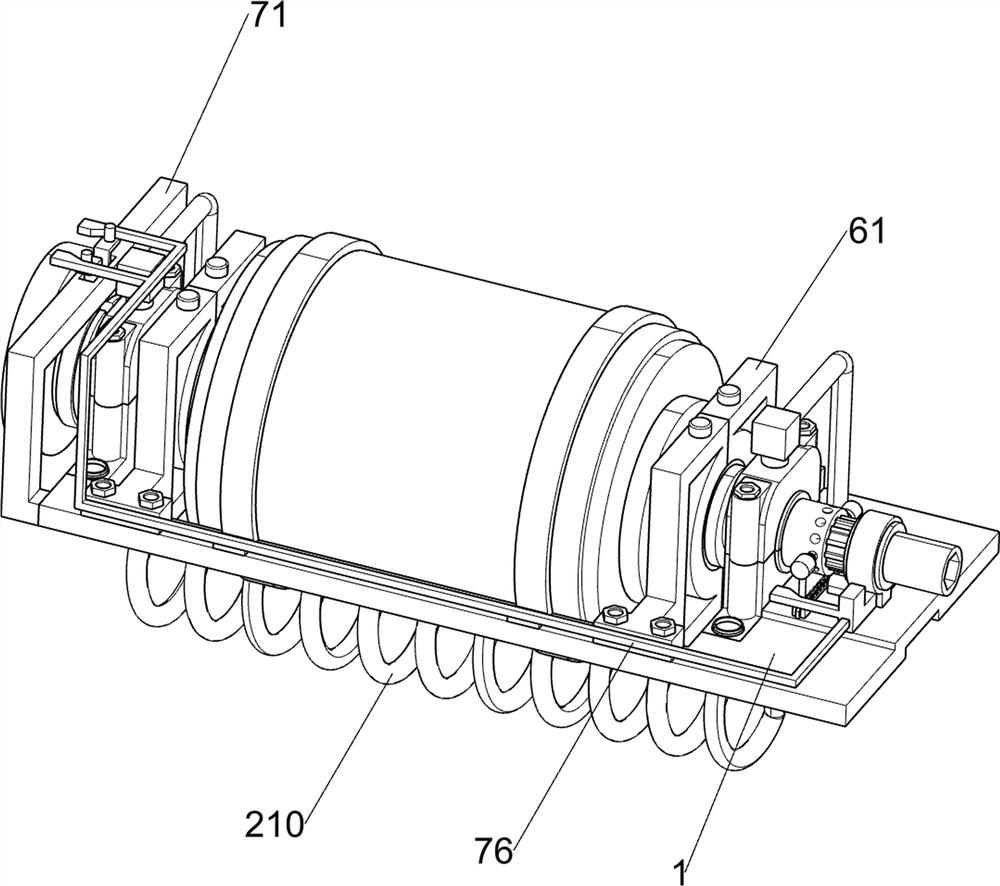
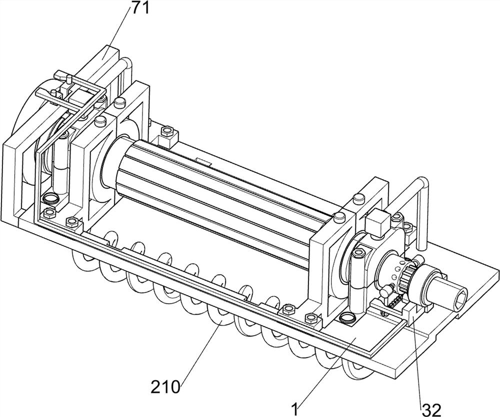
[0042] A high-speed drive motor shaft for a new energy vehicle, as shown in Figure 1, Figure 2, Figure 3, Figure 4, Figure 5, Figure 6, Figure 7, Figure 8, Figure 9,

[0045] The position calibration component 4 includes a guide rail 41, a movable seat 42, a guide sleeve 43, a cylindrical clamping rod 44, a clamping spring 45 and

Embodiment 2

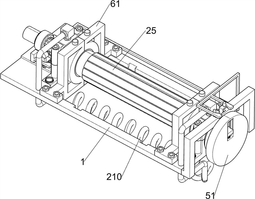
[0049] On the basis of Embodiment 1, as shown in Figure 14 and Figure 15, also includes a heat dissipation power adjustment component 5, the heat dissipation power

Embodiment 3


PUM


Abstract

The present invention relates to the field of new energy vehicles, in particular to a high-speed drive motor shaft for new energy vehicles, including a U-shaped connecting plate, a high-speed lubricating and cooling component, a power cut-off component, and a position calibration component; the U-shaped connecting plate is provided with Lubricating and cooling high-speed drive components, power cut-off components on the U-shaped connecting plate, and position calibration components on the U-shaped connecting plate. Through the cooperation of the cylindrical support roller, the ball and the upper device, since the cylindrical support roller supports the shaft body of the high-speed motor longitudinally, the shaft body of the high-speed motor can bear a large impact force, and because the ball supports the shaft body of the high-speed motor laterally, The frictional force of the high-speed motor shaft can be reduced during high-speed rotation, and the longitudinal support and horizontal support cooperate with each other, so that the high-speed motor shaft can guarantee high-speed rotation while bearing multi-directional centrifugal force, ensuring the high-speed motor shaft Safe and stable high-speed rotation.

Description

A high-speed drive motor shaft for new energy vehicles technical field [0001] The present invention relates to the field of new energy vehicles, in particular to a high-speed drive motor shaft of a new energy vehicle. Background technique In recent years, the rapid development of new energy vehicles, motor as the power source of new energy vehicles, wherein the motor bearing is A special bearing specially applied to the motor, and the motor shaft is an important part in the motor, as the motor and the device. It is the link of electromechanical energy conversion between equipment, which is used to support rotating parts, transmit torque and determine the force of rotating parts to stator. relative position, and the motor shaft will rotate at high speed, therefore, the motor shaft must have reliable strength and rigidity to ensure the preset Implementation of design functions. The motor shaft has an inseparable relationship with the high-speed motor, and the motor s...

Claims


Application Information

Patent Timeline
Patent Type & Authority Patents(China)
IPC IPC(8): F16C3/02F16D1/08F16H57/00F16H57/04F16D65/06F16D65/14H02K7/00H02K9/193F16D121/14
CPCF16C3/02F16D1/08F16H57/0025F16H57/0037F16H57/0417F16H57/0413F16H57/043F16H57/0434F16D65/06F16D65/14H02K7/003H02K9/193F16D2121/14Y02T10/64
Inventor 武瑞娜
Owner HANGZHOU SAIQI MACHINERY CO LTD
Why Eureka
Try Eureka