
Rail type bed-bed transfer device

A transfer device and track-type technology, which is applied in the field of lifting devices for patients or disabled people, can solve the problems of limiting the scope and degree of clinical application, secondary injuries of the person being carried, and difficulties in clinical work, etc., so as to achieve easy assembly and operation, reduce Risk of secondary injury, highly scalable effect

Pending Publication Date: 2022-01-14
GENERAL HOSPITAL OF TIANJIN MEDICAL UNIV
View PDF0 Cites 0 Cited by
  • Summary
  • Abstract
  • Description
  • Claims
  • Application Information

AI Technical Summary

Problems solved by technology

During the transportation process, due to the different weights of the persons being carried, the use of various pipelines and instruments, the carrying work has certain requirements on the physical strength, skills and number of personnel of the carriers, which is sometimes difficult to meet, which brings certain difficulties to the clinical work.
In addition, it is easy to cause secondary damage to the person being carried during the handling process
In response to these problems, some related device designs exist, but because of the complex structure and the need for auxiliary electrical equipment, the scope and degree of clinical application are limited.

Method used


Image

  • Rail type bed-bed transfer device
  • Rail type bed-bed transfer device
  • Rail type bed-bed transfer device

Examples


Embodiment 1

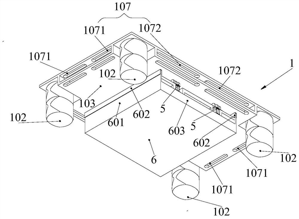
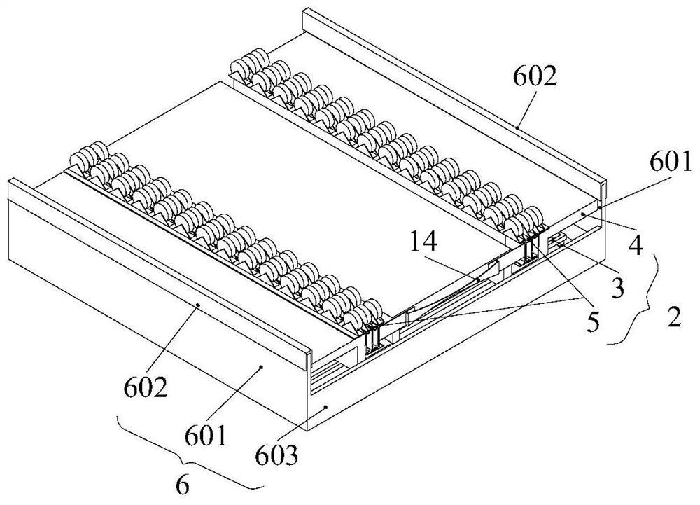
[0060] A rail-type bed transfer device, comprising a stretcher 1 and a rail lifting device 2; the stretcher 1 includes a front side 101 of the stretcher on which the patient lies and a back side 103 of the stretcher provided with a first lifting device 102, the first lifting The device 102 is used to adjust the distance between the stretcher 1 and the bed surface of the hospital bed, so that the distance matches the thickness of the rail lifting device 2, so that the rail lifting device 2 can be inserted between the stretcher 1 and the bed surface of the hospital bed; 2 includes a second lifting device 3 for raising the height of the stretcher 1, a track plate 4 rotatably connected to the second lifting device 3, and a slide rail 5 arranged on the track plate 4, and the stretcher 1 is set on the slide during bed transfer. On the rail 5, use the second lifting device 3 to adapt the height of the stretcher 1 to the bed surface of the hospital bed to be transferred, and push the s...

Embodiment 2

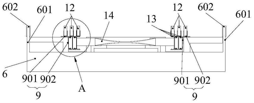
[0064] On the basis of Embodiment 1, it is further considered that the slide rail 5 can be stretched to extend the length of the slide rail so that it can adapt to more bed transfer scenarios. The slide rail 5 can be selected from commercially available and Pull-out rails with suitable weight. Described slide rail 5 comprises fixed plate 9, one group of fixed rails 10, one or more groups of slide rails 11 and the pulley 12 that is arranged on fixed rail 10 or slide rail 11 tops, and described fixed plate 9 comprises and track plate 4 The horizontal fixed plate 901 connected to the positive side and the vertical fixed plate 902 connected to the track groove 401 , the fixed rail 10 is connected to the vertical fixed plate 902 , and the sliding rail 11 is slidably connected to the fixed rail 10 .

[0065] The fixed rail 10 includes an opposite fixed inner rail, the sliding rail 11 includes a first sliding outer rail 1101, the fixed inner rail matches the first sliding outer rail ...

Embodiment 3

[0071] On the basis of Embodiment 2, the lifting rod 702 is a gas spring, and the gas spring includes supporting gas springs arranged at four corners of the supporting frame 701 . One end of the supporting gas spring is fixed to the inner side of the base 6 and the other end is connected to the universal joint 704 arranged on the back side of the supporting frame 701 . The supporting gas spring is a self-locking gas spring or a free gas spring.

[0072] Alternatively, the gas spring also includes an auxiliary gas spring whose two ends are connected to the support frame 701 and the base 6 through a universal joint, not shown in the figure, and the auxiliary gas spring is a free type gas spring.

[0073] In the special case of uneven ground, it is necessary to adjust the angle of the stretcher to maintain the horizontal state of the patient during the transfer of the bed. The supporting gas springs at the four corners can be adjusted separately so that the stretcher can be lifte...


PUM


Abstract

The invention provides a rail type bed-bed transfer device, and belongs to the field of devices for lifting patients or disabled people. The rail type bed-bed transfer device comprises a stretcher and a track lifting device, wherein the stretcher comprises a stretcher front side on which a patient lies and stretcher back sides on which first lifting devices are arranged, and the first lifting devices are used for adjusting the distance between the stretcher and the surface of a sickbed, so that a rail lifting device is inserted between the stretcher and the surface of the sickbed; and the rail lifting device comprises a second lifting device used for lifting the height of the stretcher, a rail plate rotationally connected with the second lifting device and sliding rails arranged on the rail plate. Through combined application of the split stretcher and the rail lifting device, a patient can be transferred between beds. The transfer device is simple and convenient in structure and easy to disassemble, and bed-bed transfer of patients can be completed by 2-3 persons. Bed-bed transfer of various height differences can be realized. The requirements for butt-jointed bed-bed transfer at various angles can also be met, and the transfer is not limited by the size of a transfer space.

Description

technical field [0001] The invention belongs to the field of devices for lifting patients or disabled persons, and in particular relates to a rail-type bed transfer device. Background technique [0002] At present, the bed-bed transfer of clinical bedridden patients or critically ill patients mostly adopts the way of multiple people working together with bare hands. During the transportation process, due to the different weights of the persons being carried and the use of various pipelines and instruments, the carrying work has certain requirements on the physical strength, skills and number of personnel of the carriers, which is sometimes difficult to meet and brings certain difficulties to clinical work. In addition, it is easy to cause secondary damage to the person being carried during the handling process. In response to these problems, there are some existing related device designs, but because of the complex structure and the need for auxiliary electrical equipment, ...

Claims


Application Information

Patent Timeline
Patent Type & Authority Applications(China)
IPC IPC(8): A61G7/14
CPCA61G7/1042A61G7/1034A61G7/1036A61G7/1057
Inventor 李洁
Owner GENERAL HOSPITAL OF TIANJIN MEDICAL UNIV
Learn More