Intelligent terminal crimping device
A terminal crimping and intelligent technology, applied in the direction of connection, electrical components, circuits, etc., can solve the problems of time-consuming, labor-consuming, time-consuming, and plugging, and achieve the effect of convenient docking and simple and convenient operation.
- Summary
- Abstract
- Description
- Claims
- Application Information
AI Technical Summary
Problems solved by technology
Method used
Image

Examples
Embodiment 1
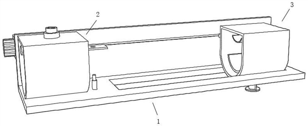
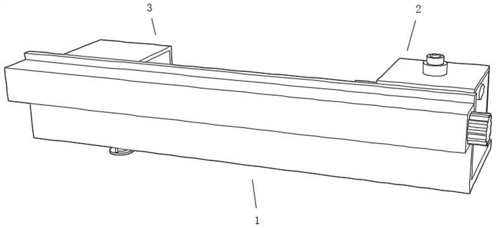
[0030] Such as figure 1 , Figure 5 as well as Figure 6 As shown, the present invention provides a technical solution: an intelligent terminal crimping device, including a frame mechanism 1, on which an adjustable crimping mechanism 2 and an adjustable wire harness fixing mechanism 3 are sequentially arranged from left to right , the adjustable crimping mechanism 2 is provided with an adjusting mechanism 5, and the frame mechanism 1 between the adjustable crimping mechanism 2 and the adjustable wire harness fixing mechanism 3 is provided with an auxiliary telescopic rod 4, and the adjustable crimping mechanism 2 includes a workpiece Place the frame 21, and the workpiece placement frame 21 is provided with a small hydraulic assembly 22, a crimping column 23 and an auxiliary adjustment plate 24 in sequence from top to bottom, and an adjusting mechanism 5 is provided on both sides of the crimping column 23, and the adjusting mechanism 5 includes an arc The automatic fixing pla...
Embodiment 2
[0033] Such as Figure 4As shown, the adjustable wire harness fixing mechanism 3 includes a cable placement frame 31, and the interior of the cable placement frame 31 is sequentially provided with a No. The top of the electric telescopic rod 32 is installed on the inner top of the cable placement frame 31, and the output end of the No. 1 electric telescopic rod 32 is fixedly connected with the arc-shaped fixing plate 33, and the cross-sectional size of the arc-shaped fixing plate 33 is smaller than that of the arc-shaped debugging plate 34. Cross-section size, the bottom of the arc-shaped debugging board 34 is fixedly connected to the output end of the No. 2 electric telescopic rod 35, and the No. 2 electric telescopic rod 35 is movably inserted on the cable placement frame 31, and the bottom of the No. 2 electric telescopic rod 35 is welded with The mounting frame 36 is welded between the mounting frame 36 and the cable placement frame 31, the cable placement frame 31 is mova...
Embodiment 3
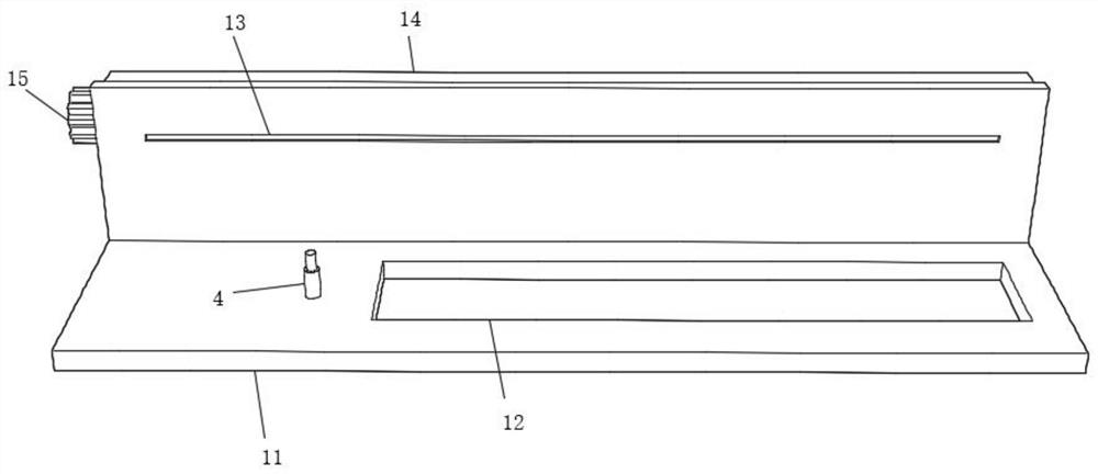
[0036] Such as Figure 1-3 As shown, the frame body mechanism 1 includes a main frame 11, a limiting groove 12, an adjusting groove 13, a housing 14 and a motor assembly 15, the limiting groove 12 is opened on the horizontal end of the main frame 11, and the vertical side of the main frame 11 An adjustment groove 13 is opened on the wall, and the adjustment groove 13 communicates with the housing 14. The housing 14 is provided with a motor assembly 15. The motor assembly 15 includes a servo motor, a threaded rod, a threaded sleeve and a bearing. The thread in the motor assembly 15 The rod is rotatably connected with the bearing on the inner wall of the housing 14, and the auxiliary telescopic rod 4 is arranged on the main frame 11 between the limiting groove 12 and the workpiece placement frame 21, and the workpiece placement frame 21 and the main frame 11 are welded.
[0037] In this embodiment, the frame mechanism 1 and the auxiliary telescopic rod 4 are provided in the pres...
PUM
 Abstract
Description
Claims
Application Information
 - R&D
- Intellectual Property
- Life Sciences
- Materials
- Tech Scout
- Unparalleled Data Quality
- Higher Quality Content
- 60% Fewer Hallucinations
Browse by: Latest US Patents, China's latest patents, Technical Efficacy Thesaurus, Application Domain, Technology Topic, Popular Technical Reports.
© 2025 PatSnap. All rights reserved.Legal|Privacy policy|Modern Slavery Act Transparency Statement|Sitemap|About US| Contact US: help@patsnap.com