
Auxiliary centering support

A centering bracket and support frame technology, applied in the field of centering, can solve the problems of short input shaft, impossibility of turning the input shaft of the reducer, difficulty in rotation, etc., and achieve the effect of ensuring stable readings

Pending Publication Date: 2021-12-24
MCC BAOSTEEL TECH SERVICE
View PDF0 Cites 0 Cited by
  • Summary
  • Abstract
  • Description
  • Claims
  • Application Information

AI Technical Summary

Problems solved by technology

For couplings made of non-magnetic adsorption materials such as stainless steel, the magnetic support cannot be fixed on the flange end face of the coupling, so that the laser alignment instrument cannot be installed, and the chain support can only rotate synchronously There are obvious advantages when the two half-couplings are aligned: but in the actual use process, it is found that some reducer input shafts are inconvenient or difficult to rotate (that is, the input shaft of the reducer cannot be turned or turned difficult), However, the existing magnetic sliding bracket cannot be installed on the non-magnetic adsorption half-coupling to simulate the rotation of the half-coupling, and because the exposed input shaft between the reducer and the corresponding half-coupling is relatively short, the laser The installation space of the alignment instrument is limited, and the existing laser alignment instrument fixing bracket cannot be used for installation

Method used


Image

  • Auxiliary centering support
  • Auxiliary centering support
  • Auxiliary centering support

Examples


Embodiment Construction

[0022] The implementation of the present invention is illustrated by specific specific examples below, and those skilled in the art can easily understand other advantages and effects of the present invention from the content disclosed in this specification.

[0023] see Figure 1 to Figure 7 . It should be noted that the structures, proportions, sizes, etc. shown in the drawings attached to this specification are only used to match the content disclosed in the specification, for those who are familiar with this technology to understand and read, and are not used to limit the implementation of the present invention. Limiting conditions, so there is no technical substantive meaning, any modification of structure, change of proportional relationship or adjustment of size, without affecting the effect and purpose of the present invention, should still fall within the scope of the present invention. The disclosed technical content must be within the scope covered. At the same tim...


PUM


Abstract

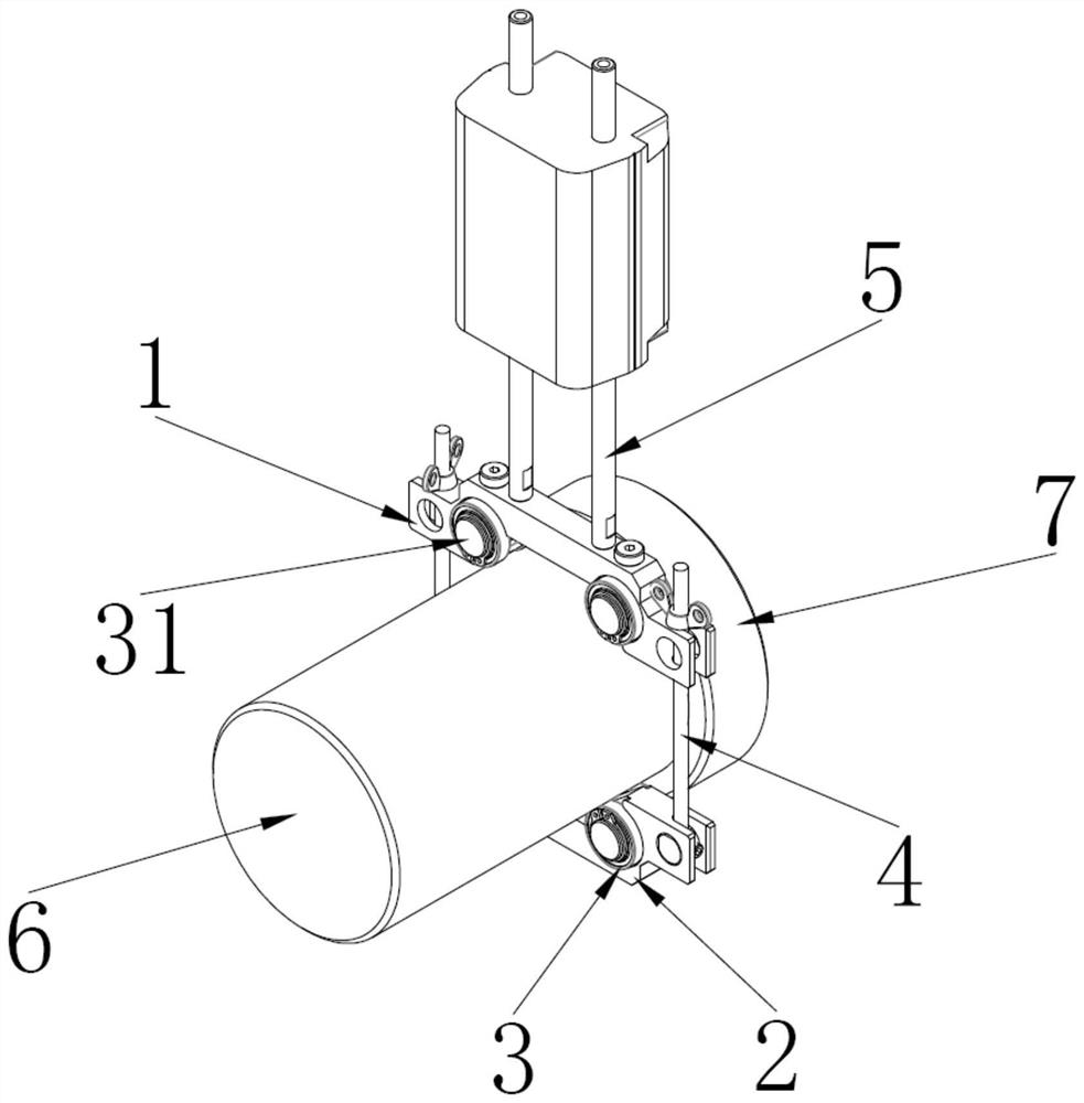
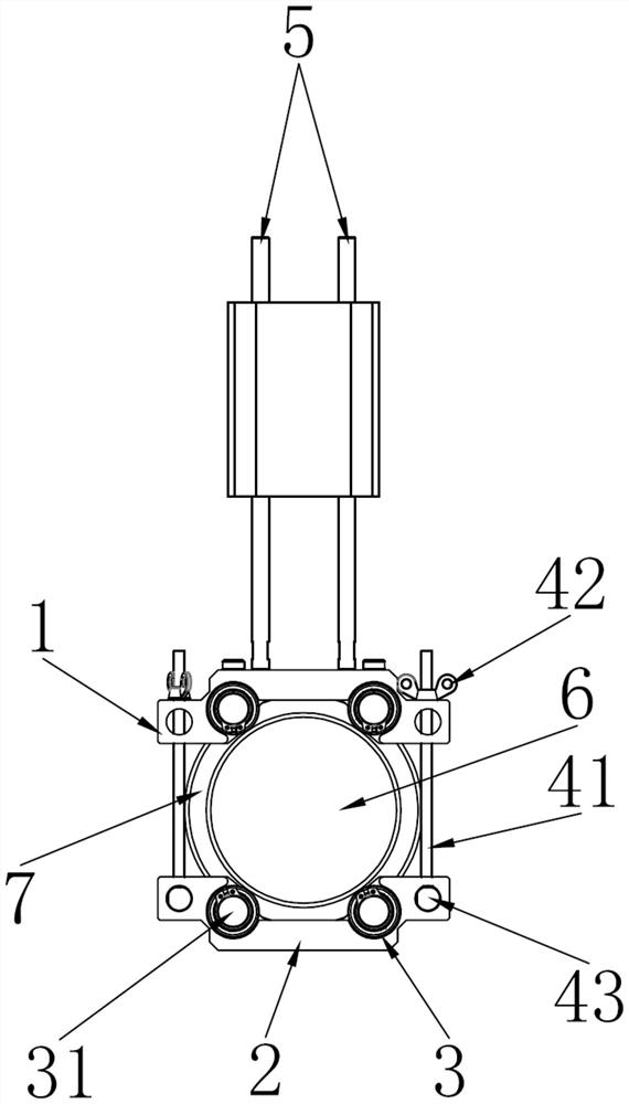
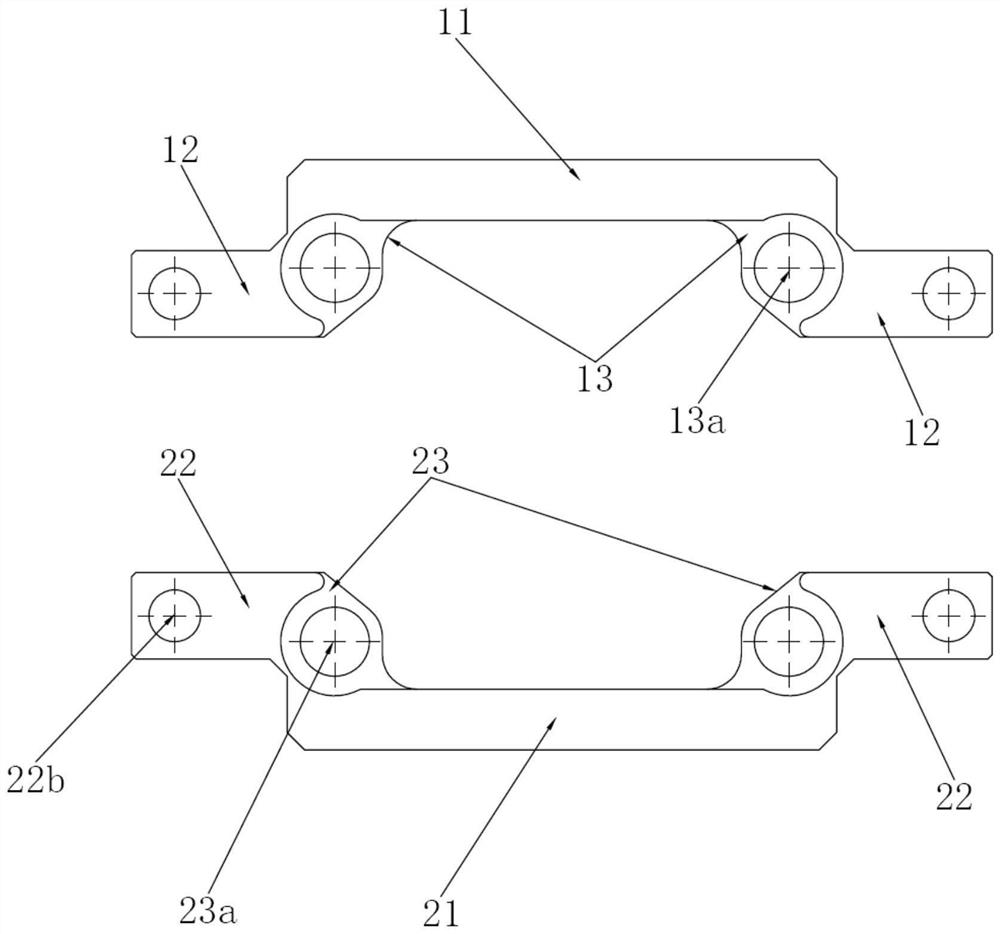
The invention provides an auxiliary centering support which comprises an upper supporting frame used for installing a laser centering instrument and a lower supporting frame matched with the upper supporting frame, the two ends of the upper supporting frame and the two ends of the lower supporting frame are connected through adjusting devices, and follow-up bearings matched with a shaft to be measured are oppositely arranged on the inner surface of the upper supporting frame and the inner surface of the lower supporting frame. The upper supporting frame and the lower supporting frame are respectively provided with at least two follow-up bearings in a rotating mode, and the center lines of the follow-up bearings are parallel to the axis of the shaft to be measured. Through cooperation of the upper support frame, the lower support frame and the adjusting device, the clamping degree of the upper support frame and the lower support frame is adjusted, so that the upper support frame and the lower support frame can be stably fixed on a shaft to be measured, and stable reading of the laser centering instrument is ensured; follow-up bearings arranged on the inner surfaces of the upper and lower support frames can assist the upper and lower support frames to rotate on the shaft to be measured so as to simulate the rotation of the shaft to be measured and obtain the centering deviation of the shaft to be measured and the motor shaft, thereby ensuring the centering precision of the two shafts.

Description

technical field [0001] The invention belongs to the field of centering technology, and in particular relates to an auxiliary centering support for assisting in obtaining the centering deviation between the input shaft of a reducer and the shaft of a motor that cannot be cranked or is difficult to crank. Background technique [0002] In the motor and reducer installation project, a laser alignment instrument is often used instead of a dial indicator to align the two half-couplings installed on the motor shaft and the reducer input shaft respectively, so as to realize the input of the motor shaft and the reducer. The alignment of the shaft, the alignment of the two half-couplings is actually to make the two half-couplings both concentric and parallel. The transmitter / receiver of the laser alignment instrument is generally fixed on the half coupling by magnetic force or chain fixation. For couplings made of non-magnetic adsorption materials such as stainless steel, the magneti...

Claims


Application Information

Patent Timeline
Patent Type & Authority Applications(China)
IPC IPC(8): G01C15/00
CPCG01C15/004
Inventor 陈勇陆亮李泽选李永胜马利祥
Owner MCC BAOSTEEL TECH SERVICE
Learn More