
Gradient measuring instrument for constructional engineering floor tiles

A technology for measuring instruments and construction engineering, which is applied in the direction of instruments, measuring devices, measuring inclination, etc., which can solve the problems of inconvenience for measuring personnel, troublesome operation, waste of time, etc., and achieve the effect of simple measurement work

Inactive Publication Date: 2021-12-24
HUANGHE S & T COLLEGE
View PDF0 Cites 1 Cited by
  • Summary
  • Abstract
  • Description
  • Claims
  • Application Information

AI Technical Summary

Problems solved by technology

[0003] The existing detection instruments for laying floor tiles in bathrooms are usually feeler gauges and rulers. The surveyors can measure the slope of the floor tiles through the cooperation of the two. However, this method requires the surveyors to squat on the ground and lean over to read the plug. The reading of the ruler can be used to determine whether the slope of the floor tiles is standardized, which brings greater difficulty to the surveyors. In addition, the floor drain of the bathroom needs to be taken as the center during the measurement process to measure the slope of the floor tiles around it. Therefore, the surveyors need to squat frequently Going down and leaning over to detect (meaning that the measurer needs to observe the ruler frequently and take readings with the naked eye), which brings great inconvenience to the measurer;
[0004] Moreover, due to the limited length of the ruler, the floor tiles can only be detected segment by segment (the linear measurement cannot be performed in an area with any length as the radius centered on the floor drain), and the completion of the slope detection of the entire floor tile surface in the bathroom requires frequent repetition of the above. Movement, operation is too troublesome and wastes time;

Method used


Image

  • Gradient measuring instrument for constructional engineering floor tiles
  • Gradient measuring instrument for constructional engineering floor tiles
  • Gradient measuring instrument for constructional engineering floor tiles

Examples


Embodiment 1

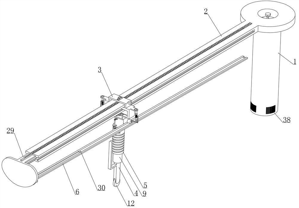
[0027] Embodiment 1, this scheme provides a kind of construction engineering floor tile slope measuring instrument, as attached figure 1 As shown, the base 1 is included and a level is provided on the base 1 (the level is not shown in the figure). When measuring the laying slope of bathroom floor tiles, the surveyor fixes the base 1 at the position of the floor drain and passes The level set on the base 1 adjusts the levelness of the base 1 (so that the base 1 is in a horizontal state to ensure the accuracy of the detection structure), the level is the prior art, and those skilled in the art combine the The design can set the level in the prior art on the base 1, and adjust the levelness of the base 1 according to the level, and when the base 1 is adjusted to a horizontal state, the surveyor will fix and position the base 1 ( to achieve subsequent measurement work);

[0028] The improvement of this scheme is that: a slide bar 2 is installed on the base 1 and a bearing frame 3...

Embodiment 2

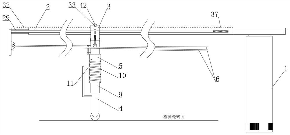
[0035] Embodiment 2, on the basis of embodiment 1, as attached figure 2 As shown, a round rod 9 is integrally provided on the lower end surface of the carrier frame 3 and vertically slides between the detection rod 4 and the round rod 9 (as attached Figure 8 shown), the detection cylinder 5 is rotatably mounted on the round rod 9, and how the detection rod 4 drives the detection cylinder 5 is described in detail below:

[0036] as attached figure 2 As shown, the outer surface of the detection cylinder 5 is provided with a spiral groove 10 and the detection rod 4 is integrally provided with a pin 11 that cooperates with the spiral groove 10 (one end of the head of the pin 11 is located in the spiral groove 10), when the detection rod 4 is opposite to the When the round rod 9 moves vertically, it will drive the detection cylinder 5 to rotate around the round rod 9 through the matching pin 11 and spiral groove 10. It is better to make the detection rod 4 collide with the end ...

Embodiment 3

[0037] Embodiment 3, on the basis of embodiment 2, as attached Figure 9 As shown, the verification device includes a rotating rod 13 that is rotatably installed on the carrier frame 3 and an arc-shaped plate 14 is slidably installed on the rotating rod 13 (a detection spring 15 is connected between the arc-shaped plate 14 and the rotating rod 13), as shown in the attached Figure 11 As shown, the upper and lower ends of the arc-shaped plate 14 are vertically slidably mounted with arc-shaped rods 22 respectively, and a collision spring 16 is connected between the arc-shaped rods 22 and the arc-shaped plates 14. A number of pressure sensors are evenly distributed on the sides. Initially (when the device is working), the side of the pressure sensors installed on the two arc rods 22 is in contact with the calibration device under the action of the conflict spring 16;

[0038] When the measurement work is started, the speed regulating device drives the rotating rod 13 to rotate (s...


PUM


Abstract

The invention relates to a gradient measuring instrument for constructional engineering floor tiles. The problems that in the existing floor tile gradient measuring process, the detection process is tedious and inconvenient, and large work intensity is brought to measuring personnel are effectively solved. According to the technical scheme, in the measuring process, a measurer does not need to carefully check a measuring tool with naked eyes, whether the gradient of a detected part meets the requirement or not can be judged only by paying attention to the state of a warning lamp, and in the measuring process, with the floor drain as the center, the gradient of the floor tile is linearly measured on the area with any length as the radius, and compared with traditional sectional detection, the gradient measuring instrument has the advantages that the precision of the detection result is greatly improved, and the reference of the detection result is higher.

Description

technical field [0001] The invention belongs to the technical field of building construction measurement, and in particular relates to an instrument for measuring the slope of building engineering floor tiles. Background technique [0002] With the continuous development of society, people's requirements for living houses are getting higher and higher, and interior decoration is becoming more and more popular among people. Among them, whether the laying of indoor floor tiles is smooth has become the object of people's more attention. For living rooms, horizontal interiors Floor tiles are required to have a higher flatness to enhance the living experience, and a certain degree of slope is required for the laying of floor tiles in the bathroom (a range, as long as it is within this range, it means that it meets the requirements of the specification) so as to facilitate the flow of water. emission; [0003] The existing detection instruments for laying floor tiles in bathrooms...

Claims


Application Information

Patent Timeline
Patent Type & Authority Applications(China)
IPC IPC(8): G01C9/00G01C9/02
CPCG01C9/00G01C9/02
Inventor 党宁亚陈学芹马志国王志成尹中秋
Owner HUANGHE S & T COLLEGE
Learn More