Dustproof tool jig for part production

A technology of tooling fixtures and parts, which is applied in the field of dust-proof tooling fixtures, which can solve the problems of difficult dust-proof devices, no protective measures, and reduced device use effects, so as to achieve the effects of dust prevention and convenient use

Pending Publication Date: 2021-12-24
苏州米品精密科技有限公司
View PDF1 Cites 0 Cited by
  • Summary
  • Abstract
  • Description
  • Claims
  • Application Information

AI Technical Summary

Problems solved by technology

", when the above-mentioned device is in use, it is difficult to achieve the dust-proof effect on the surface of the fixture, and when the device is not in use, it is difficult to achieve the dust-proof protection effect, resulting in a reduction in the use effect of the device;
[0005] 2. In the prior art, there is a dust-proof tooling fixture for parts production. When in use, the plug-in interface of the device needs to clean the dust on the surface, but most devices have no protection on the surface of the plug-in interface. measures, causing dust to enter the interface, making it difficult to effectively prevent dust inside the device

Method used


Image

  • Dustproof tool jig for part production
  • Dustproof tool jig for part production
  • Dustproof tool jig for part production

Examples


Embodiment 1

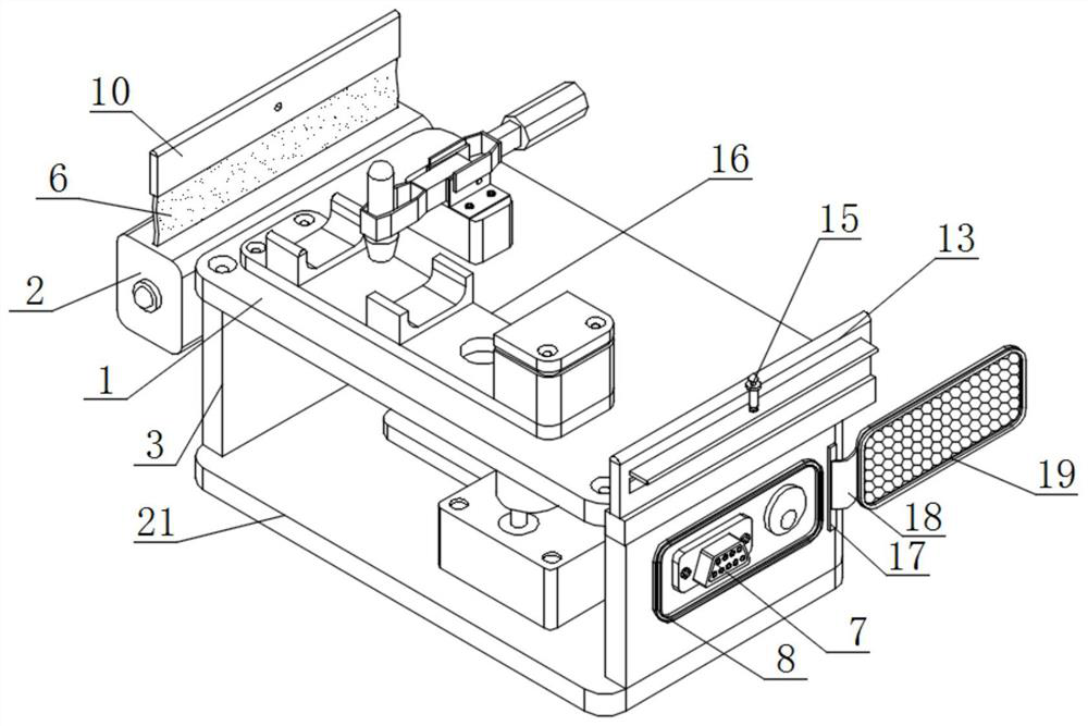
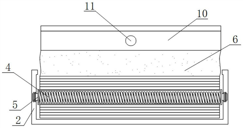
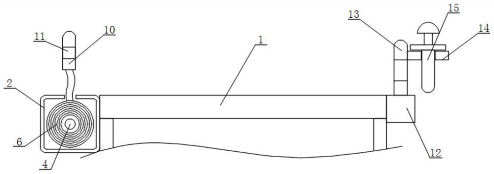
[0026] see figure 1 and figure 2 and Figure 4 , an embodiment provided by the present invention is a dust-proof tooling fixture for parts production, including a work platform 1, a wire take-up box 2 and a fixed panel 3, and a wire take-up box 2 is arranged on one side of the work platform 1, One side of the bottom of the working platform 1 is provided with a fixed panel 3, one side of the inner wall of the take-up box 2 is connected with a torsion spring 4, one side of the surface of the torsion spring 4 is connected with a winding rod 5, and one end of the winding rod 5 is connected to the The inner wall of the take-up box 2, one side of the surface of the winding rod 5 is connected with a dustproof cloth 6;

[0027] When in use, the staff needs to idle the working platform 1 of the device to prevent dust, because a take-up box 2 is installed on one side of the work platform 1, and the inside of the take-up box 2 is connected with a torsion spring 4, and the surface of t...

Embodiment 2

[0029] see figure 1 and figure 2 and image 3 and Figure 4 , an embodiment provided by the present invention, a dust-proof tooling fixture for parts production, including a plug-in interface 7, a mounting panel 8 and a fixed panel 3, one side of the surface of the fixed panel 3 is provided with a plug-in interface 7 , the middle part of the surface of the fixed panel 3 is equipped with an installation panel 8, one side of the surface of the installation panel 8 is provided with a plug-in groove 9, one side of the dustproof cloth 6 is connected with a fixed block 10, and the middle part of the surface of the fixed block 10 is provided with a plug-in slot Hole 11, a connection block 12 is installed on one side of the working platform 1, a plug-in board 13 is installed on the top of the connection block 12, and a connecting plate 14 is installed in the middle of one side of the plug-in board 13, and the middle part of the top of the connecting board 14 passes through the conn...


PUM


Abstract

The invention discloses a dustproof tool jig for part production. The dustproof tool jig comprises a working platform, a take-up box and a fixing panel, the take-up box is arranged at one side of the working platform, the fixing panel is arranged at one side of the bottom of the working platform, a torsion spring is connected to one side of the inner wall of the take-up box, a winding rod is connected to one side of the surface of the torsion spring, one end of the winding rod is connected to the inner wall of the take-up box through a rotating shaft, dustproof cloth is connected to one side of the surface of the winding rod, a plug-in interface is formed at one side of the surface of the fixing panel, and a mounting panel is mounted in the middle of the surface of the fixing panel. An inserting groove is formed at one side of the surface of the mounting panel. According to the jig, through the arrangement of the fixing panel, the plug-in interface, the mounting panel, the inserting groove, a connection block, a movable rope, a sealing cover and a sealing block, the plug-in interface is sealed, dust is prevented from entering the plug-in interface, and the plug-in interface is convenient to use.

Description

technical field [0001] The invention relates to the technical field of tooling fixtures, in particular to a dust-proof tooling fixture for parts production. Background technique [0002] Fixtures are a large category of tools for woodworking, ironwork, fitters, machinery, electric control and other handicrafts. They are mainly used as a tool to assist in controlling position or movement. Fixtures can be divided into process assembly fixtures, project There are three types of test fixtures and circuit board test fixtures. [0003] In the prior art, a kind of dust-proof tooling fixture used for parts production has disadvantages: [0004] 1. The comparative document CN208977648U discloses a tooling fixture, including "support seat and positioning piece, the support seat is provided with a profiling groove, the profiling groove is used to accommodate and fix the battery of the electronic device, the The positioning piece is used to cooperate with the positioning hole provided...

Claims


Application Information

Patent Timeline
IPC IPC(8): B25H1/00B65H75/48B08B17/04
CPCB25H1/00B65H75/48B08B17/04
Inventor 吕美芳
Owner 苏州米品精密科技有限公司
Why Eureka
Try Eureka