
Resonant switching power converter

A power converter, switching technology, applied in the direction of output power conversion devices, conversion equipment without intermediate conversion to AC, electrical components, etc., can solve problems such as large surge currents, reduce surge currents, and improve power supply Efficiency, the effect of reducing power loss

Active Publication Date: 2021-12-21
RICHTEK TECH
View PDF8 Cites 1 Cited by
  • Summary
  • Abstract
  • Description
  • Claims
  • Application Information

AI Technical Summary

Problems solved by technology

The capacitance of this known power converter has a very large inrush current when the switches Q1-Q10 switch

Method used


Image

  • Resonant switching power converter
  • Resonant switching power converter
  • Resonant switching power converter

Examples


Embodiment Construction

[0115] The drawings in the present invention are all schematic diagrams, mainly intended to show the coupling relationship between various circuits and the relationship between various signal waveforms. As for the circuits, signal waveforms and frequencies, they are not drawn to scale.

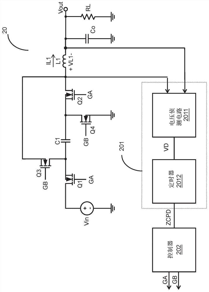
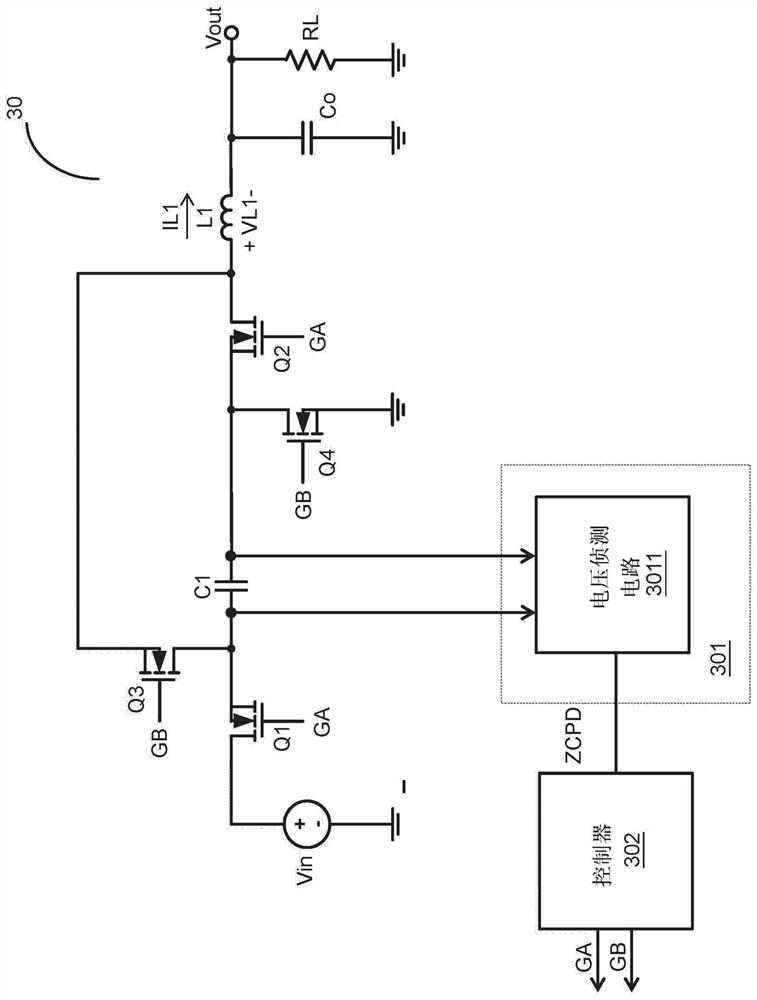
[0116] figure 2 is a schematic circuit diagram showing a resonant switching power converter according to an embodiment of the present invention. Such as figure 2 As shown, in this embodiment, the same inductance L1 is used as the charging inductance and the discharging inductance at different times, and such setting can further reduce the number of inductances. Such as figure 2 As shown, the resonant switching power converter 20 of the present invention includes a capacitor C1 , switches Q1 , Q2 , Q3 , Q4 , an inductor L1 , a zero current estimation circuit 201 and a controller 202 . Wherein, the switch Q1 is connected in series with the capacitor C1, and the switch Q2 is connected in serie...


PUM


Abstract

A resonant switching power converter includes: at least one capacitor; a plurality of switches coupled to the at least one capacitor and switching electrical connection relationships of capacitors according to an operation signal; at least one charging inductor; at least one discharging inductor; and a zero current estimation circuit coupled to the at least one charging inductor and / or the at least one discharging inductor and / or the capacitor and used for estimating a time point at which a charging resonant current is zero during a charging process and / or estimate a time point at which a discharging resonant current is zero during at least one discharging process according to voltage differences across two ends of the charging inductor and / or the discharging inductor, so as to correspondingly generate a zero current estimation signal. The zero current estimation signal is adopted to generate an operation signal.

Description

technical field [0001] The present invention relates to a resonant switching power converter, in particular to a resonant switching power converter capable of estimating the time point of zero current. Background technique [0002] Figure 1 shows a known power converter. During the charging operation, the switches Q1, Q2, Q3, and Q4 are turned on, and the switches Q5, Q6, Q7, Q8, Q9, and Q10 are not turned on, so that the capacitors C1, C2, and C3 are connected in series between the input voltage Vin and the output voltage Vout. between. In the discharge operation, the switches Q5, Q6, Q7, Q8, Q9, and Q10 are turned on, and the switches Q1, Q2, Q3, and Q4 are not turned on, so that the capacitors C1, C2, and C3 are connected in parallel between the ground potential and the output voltage Vout . The capacitance of the known power converter has a very large inrush current when the switches Q1-Q10 switch. [0003] In view of this, the present invention proposes an innovativ...

Claims


Application Information

Patent Timeline
IPC IPC(8): H02M3/07H02M1/32
CPCH02M3/07H02M1/32Y02B70/10
Inventor 刘国基杨大勇白忠龙
Owner RICHTEK TECH
Learn More