Combined fire extinguishing system of unmanned aerial vehicle and multi-degree-of-freedom mechanical arm fire extinguishing robot

A technology of fire-fighting robot and fire-fighting system, which is applied in the field of joint fire-fighting system of unmanned aerial vehicles and multi-degree-of-freedom manipulator fire-fighting fire-fighting robots, which can solve problems that affect fire-fighting efficiency, fail to achieve better fire-fighting effects, and cannot carry fire-fighting water, etc. , to achieve the effect of easy operation

Inactive Publication Date: 2021-12-21
青岛澳西智能科技有限公司
View PDF0 Cites 1 Cited by
  • Summary
  • Abstract
  • Description
  • Claims
  • Application Information

AI Technical Summary

Problems solved by technology

The two water supply methods have their own advantages and disadvantages, and are suitable for different occasions
The water supply method of the water tank can avoid dragging heavy water pipes and improve the flexibility of the UAV. However, the volume of the water tank is limited by the robot’s dynamic performance, and it cannot carry enough fire-fighting water. It is necessary to continuously replenish the water tank, which affects the fire-fighting efficiency; Although the way of water pipes can meet the demand for continuous water use, it still cannot achieve a good fire-fighting effect when the fire-fighting operation of super-high-rise buildings exceeds the height of the water pump lift of the fire truck.
During forest fire operations, drones cannot carry out fire hose operations

Method used


Image

  • Combined fire extinguishing system of unmanned aerial vehicle and multi-degree-of-freedom mechanical arm fire extinguishing robot
  • Combined fire extinguishing system of unmanned aerial vehicle and multi-degree-of-freedom mechanical arm fire extinguishing robot
  • Combined fire extinguishing system of unmanned aerial vehicle and multi-degree-of-freedom mechanical arm fire extinguishing robot

Examples


Embodiment 1

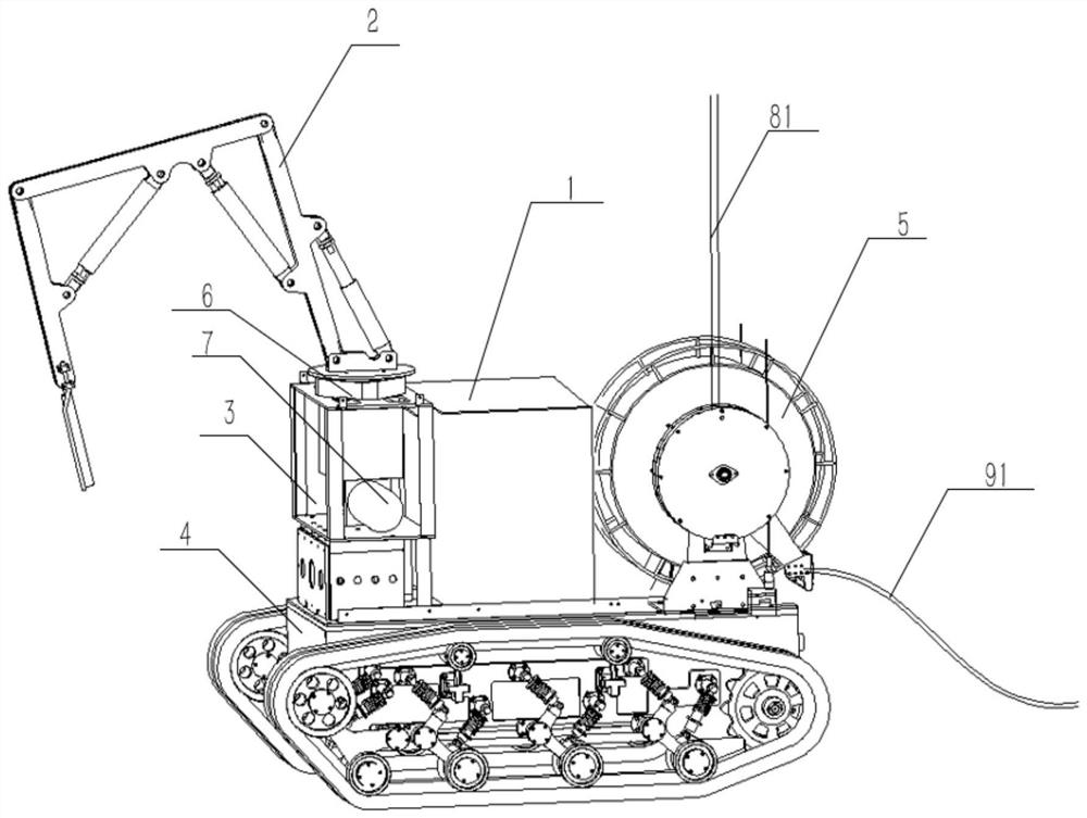
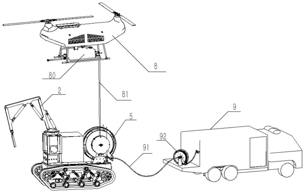
[0063] In the present embodiment, the first end of the first water pipe 91 connects the water supply joint 90 of the water supply vehicle 9, the end connection of the second water pipe 81 on the first roll 5; the fire extinguishing robot is in the process of travel, the second reap The first water pipe 91 mounted on 92, the second water pipe 81 mounted on the first roll 5, the first roll 5, the second roll 92 is provided with a coil spring, maintaining the second water pipe 81, The first water pipe 91 is always wound during the tightening process.

[0064] When the end of the second water pipe 81 is connected to the first water supply mechanism 80 of the drone 8, the water supply vehicle 9 is the first water supply mechanism 80 of the drone 8 in real time water supply; the end of the second water pipe 81 is connected to the firefighting robot. When the second water supply mechanism is 1, the water supply vehicle 9 is supplied in real time for the second water supply mechanism of f...

Embodiment 2

[0066] The first water supply mechanism 2 is provided with: the second spray gun 806 and a water tank 805 provided with a plurality of inlet portions and water outlets. The water tank 805 is connected to the first line 8021, the second line 8022, the third line 8023, the fourth line 8024, the first line 8021, the second line 8022, the third pipe 8023, the first In the four-channel 8024, the first end is the upstream direction of the water flow, and the end is the downstream direction of the water flow.

[0067] When the end of the second water pipe 81 is coupled, the first end of the end of the end of the second water pipe 81 is first line 8021.

[0068] The end of the first line 8021 is connected to the water tank 805 water outlet; the first end of the second line 8022 is connected to the water tank 805 outlet, the end is connected to the second spray gun 806; the third line 8023 is first connected to the water tank 805 outlet, end Connect to the second pipe 8022; the first end o...

Embodiment 3

[0072] In this embodiment, no one is responsible for using the second spray gun 806 to perform the injection fire extinguishing fire, the end of the second water pipe 81 is connected to the first water supply mechanism 80 of the drone 8, and the robot is responsible for dragging the water belt to follow the inorganic movement, and pass The first spray gun 27 injection combined with fire extinguishing. The fire fire extinguishing robot is provided with a related processor and motion control module, and the transmitting device and the drone positioning tracking device 401 are communicated by electromagnetic waves when the transmission device, the transmitting device, and the drone positioning tracking device 401 communication is communicated. Time measuring the distance of the drone to the fire extinguishing robot, calculates the direction of the drone relative to the fire extinguishing robot by measuring the phase difference on the micro antenna array, and the information is given ...


PUM


Abstract

The invention relates to the technical field of fire fighting robots, and provides a combined fire fighting system of an unmanned aerial vehicle and a multi-degree-of-freedom mechanical arm fire fighting robot. The combined fire fighting system comprises: an unmanned aerial vehicle loaded with a first water supply mechanism; a water supply vehicle which is provided with a second reel; and a fire-fighting robot which is provided with a first reel, a second water supply mechanism, a mounting seat and a mechanical arm mechanism. The multi-degree-of-freedom mechanical arm mechanism composed of three mechanical arms and three telescopic arms and used for carrying a spray gun is designed, and the multi-degree-of-freedom spraying angle adjustment of the spray gun can be achieved through the mechanical arm mechanism. The fire extinguishing machine carrying the first reel and the water supply vehicle provided with the second reel are arranged, the water supply vehicle selects a fire extinguishing robot or an unmanned aerial vehicle for fire extinguishing, and the robot moves in different directions along with the unmanned aerial vehicle. The combined operation of the unmanned aerial vehicle, the fire-fighting robot and the water supply vehicle is realized, and the fire-fighting operation requirements in a complex environment are met with high quality.

Description

Technical field [0001] The present invention relates to the technical field of fire extinguishing robots, specifically a joint fire protection system for drone and multi-freedom robot firefighting robots. Background technique [0002] The fire fire extinguishing robot is a special robot, and it is possible to play a pivotal role in fire relief. In the process of firefighter rescue task, the device can accurately determine the area of ​​fire fighting, and use the most intelligent and most convenient mode to fire extinguishment, help fire fighting rescue work smoothly, and greatly reduce firefighters to perform tasks. risk. However, the current fire fire extinguishing robot only carries a fixed spray gun, fire extinguishing height, limited fire extinguishing angle, and is suitable. [0003] On the other hand, with the development of my country's economic and social, high-rise buildings have gradually become the mainstream form of architecture. In the fire rescue mission, high-rise ...

Claims


Application Information

Patent Timeline
IPC IPC(8): A62C27/00A62C31/03A62C31/28A62C33/04A62C37/00B64C39/02B25J9/16B25J11/00B25J18/02
CPCA62C27/00A62C31/03A62C31/28A62C33/04A62C37/04B64C39/024B25J11/00B25J9/1689B25J18/025
Inventor 王磊吕建龙张兴起付国新丁明文王文杰
Owner 青岛澳西智能科技有限公司
Why Eureka
Try Eureka