Remote monitor based on Internet of Things
A monitor and Internet of Things technology, applied in the direction of supporting machines, pollution prevention methods, chemical instruments and methods, etc., can solve problems such as operating hazards, operator injuries, and high installation positions, so as to improve firmness, facilitate monitoring, and reduce The effect of pressure
- Summary
- Abstract
- Description
- Claims
- Application Information
AI Technical Summary
Problems solved by technology
Method used
Image

Examples
Embodiment 1
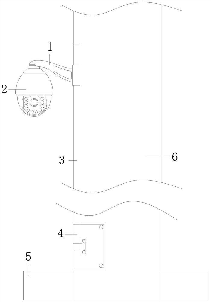
[0031] see figure 1 , the present invention provides a remote monitor based on the Internet of Things, the structure of which includes a support frame 1, a monitoring device 2, a dustproof device 3, an inspection door 4, a base 5, and a column 6, and a column 6 is installed at the center of the top of the base 5, An inspection door 4 is installed on one side of the column 6, and a dust-proof device 3 is installed on the same side of the column 6 and the inspection door 4, and the dust-proof device 3 is installed on the top of the inspection door 4, and the dust-proof device 3 is connected to the monitoring equipment 2 through the support frame 1 .
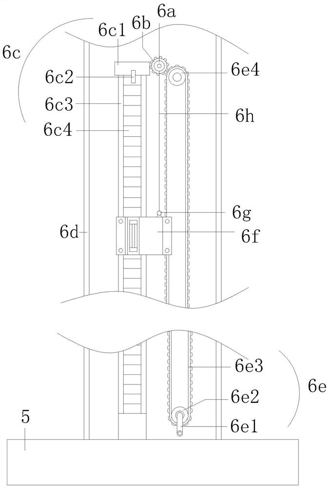
[0032] see Figure 2-3 , the specific column 6 includes a reel 6a, a gear 6b, an engaging mechanism 6c, a column body 6d, a conveying mechanism 6e, a fixing mechanism 6f, a hook 6g, and a traction rope 6h, and an engaging mechanism is installed inside the column body 6d 6c, the conveying mechanism 6e, the fixing mechanism 6f is ...
Embodiment 2
[0038] see Figure 4 , the fixing mechanism 6f recorded in the first implementation includes a limit line 6f1, a fixed pulley 6f2, a moving structure 6f3, a moving rod 6f4, a mounting block 6f5, a soft rubber block 6f6, a second gear 6f7, and a moving frame 6f8. The moving frame 6f8 is away from One end of the limit block 6c4 is provided with a moving structure 6f3 and an installation block 6f5, two installation blocks 6f5 are provided, and two threaded holes are arranged on the top of the installation block 6f5, and the movement structure 6f3 is arranged between the two installation blocks 6f5. The bottom of the structure 6f3 is equipped with a moving rod 6f4. The end of the moving rod 6f4 away from the moving structure 6f3 is connected to the limit line 6f1. The limit line 6f1 is attached to the soft rubber block 6f6 through the fixed pulley 6f2. There are four fixed pulleys 6f2. The soft rubber block 6f6 is installed inside the moving frame 6f8, and the bottom of the moving...
Embodiment 3
[0045] see Figure 6-7 , the dustproof device 3 that records in the embodiment one comprises No. 1 fixed plate 3a, inclined plate 3b, No. 2 fixed plate 3c, spring 3d, No. 3 magnetic block 3e, dustproof cloth 3f, No. 1 fixed plate 3a, No. 2 fixed plate The No. 1 fixed plate 3c is connected with the column body 6d by a hinge, the No. 1 fixed plate 3a is equipped with a No. 3 magnetic block 3e at one end away from the column body 6d, and the bottom of the No. 1 fixed plate 3a is provided with a slant plate 3b, and the slant plate 3b is connected to the column by a spring 3d. The bodies 6d are connected, the No. 2 fixed plate 3c is installed on the top of the No. 1 fixed plate 3a, and a dustproof cloth 3f is installed between the bottom of the No. 1 fixed plate 3a and the top of the No. 2 fixed plate 3c.
[0046] The function of the above-mentioned inclined plate 3b is that when the No. 1 fixed plate 3a is pushed down by the support frame 1, the No. 1 fixed plate 3a pushes the inc...
PUM
 Abstract
Description
Claims
Application Information
 - R&D
- Intellectual Property
- Life Sciences
- Materials
- Tech Scout
- Unparalleled Data Quality
- Higher Quality Content
- 60% Fewer Hallucinations
Browse by: Latest US Patents, China's latest patents, Technical Efficacy Thesaurus, Application Domain, Technology Topic, Popular Technical Reports.
© 2025 PatSnap. All rights reserved.Legal|Privacy policy|Modern Slavery Act Transparency Statement|Sitemap|About US| Contact US: help@patsnap.com