Barbell with protection function

A protection function, barbell technology, applied to dumbbells, heavy objects, sports accessories, etc., can solve the problems of barbells that cannot be used alone, the protector's inattention, and the lack of magnetic resistance to replace the barbell plates.

Inactive Publication Date: 2021-12-14
陈霖毅
View PDF0 Cites 0 Cited by
  • Summary
  • Abstract
  • Description
  • Claims
  • Application Information

AI Technical Summary

Problems solved by technology

[0003] The barbell bar of the prior art has the following disadvantages: there is a gap between the barbell plate and the barbell bar, and the barbell plate needs to be fixed by a clamp in advance. , falling from a higher place, the belayer's inattention, the belayer's strength is small, etc.), it must be carried out in cooperation between the trainer and the belayer, so that the barbell cannot be used alone
[0004] And most of the existing barbells need to be used with the help of barbell plates, but there is no corresponding magnetic resistance to realize the function of replacing the barbell plates, and in the existing equipment, if the barbell falls due to lack of physical strength, it still needs The surrounding personnel manually remove the barbell plate, which cannot realize the function that a single person can push the barbell plate out of the barbell

Method used


Image

  • Barbell with protection function
  • Barbell with protection function
  • Barbell with protection function

Examples


Embodiment 1

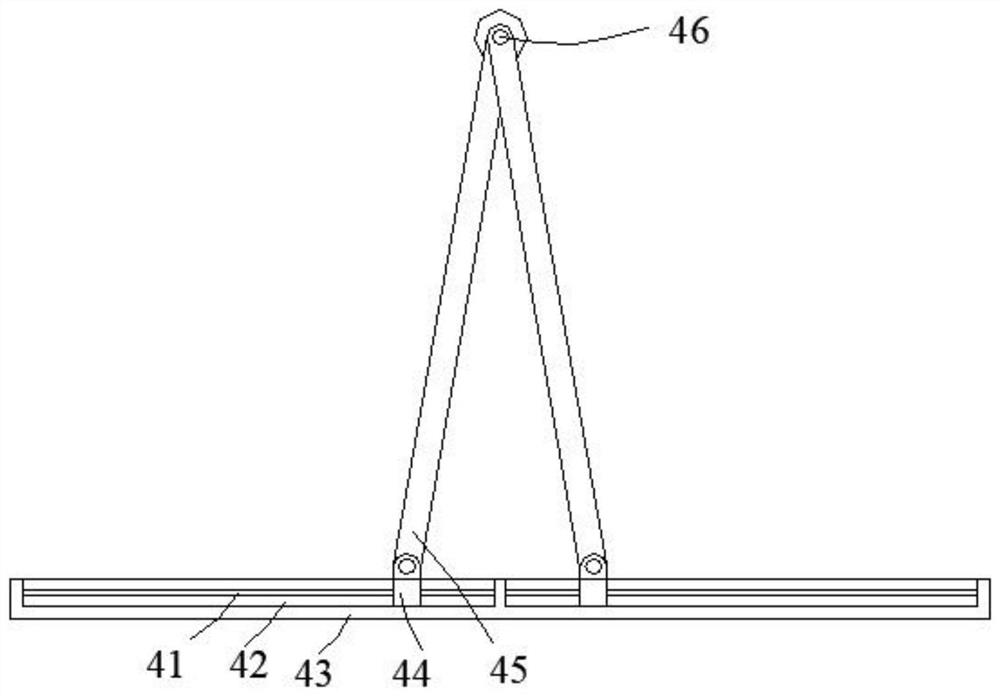
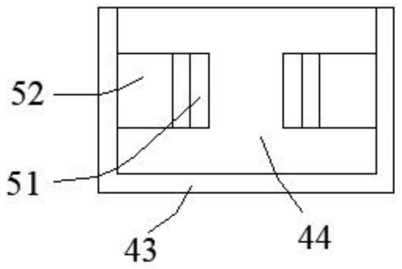
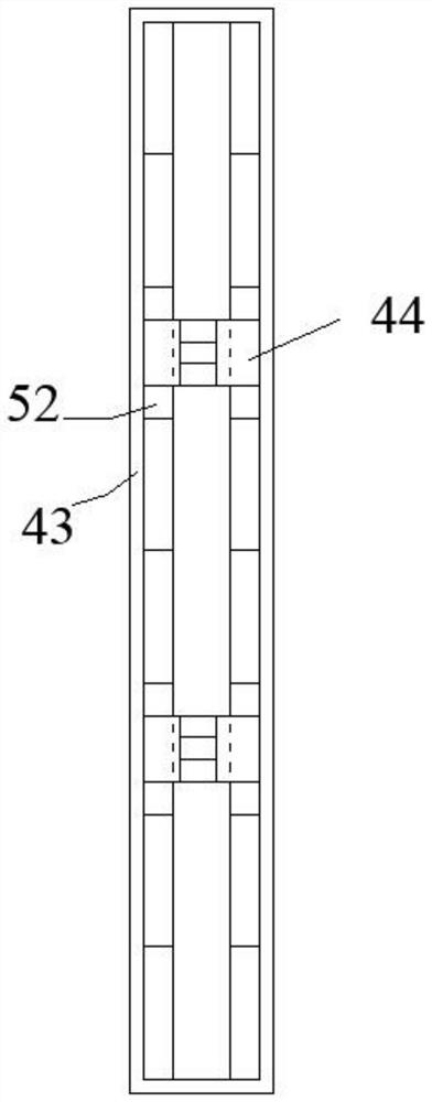
[0027] Beneficially, wherein, including the grip bar 46, the lower side of the grip bar 46 is provided with a symmetrical matching box 43, and the opening cavity 42 is arranged in the matching box body 43, and the sliding bar 41 is arranged in the opening cavity 42, and the sliding bar 41 and the opening The sliding part in the oral cavity 42 is provided with a connecting slider 44, and the connecting slider 44 is hingedly provided with a swing rod 45. The swing rod 45 is hingedly arranged with the grip rod 46. Several electromagnets 52 are arranged in the opening cavity 42, and the electromagnets 52 are arranged symmetrically. On the front and rear sides of the opening 42 , a metal block 51 is arranged in the connecting slider 44 , and the metal block 51 is magnetically attached to the electromagnet 52 .

Embodiment 2

[0029]Beneficially, wherein, including the matching handle bar 98, the lower side of the matching handle bar 98 is provided with a front and back symmetrical bottom box body 71, and both sides of the bottom box body 71 are provided with an open sliding cavity 72, and the opening sliding cavity 72 is provided with The middle rod 73, sliding in the opening sliding cavity 72 is provided with a sliding fitting block pushing inclined surface 81, the sliding fitting block pushing inclined surface 81 is connected with the middle rod 73 by sliding fit, and the sliding fitting block pushing inclined surface 81 is hingedly provided with an outer rotation rod 82, the outer side rotating rod 82 is hingedly set with the matching grip rod 98, the opening sliding chamber 72 is provided with a limiting device capable of limiting the range of movement of the sliding mating block pushing the inclined surface 81, and the outer side of the grip rod 98 is threaded and connected. The threaded screw ...


PUM


Abstract

The invention discloses a barbell with protection function. The barbell with the protection function structurally comprises a matched holding rod, the lower side of the matched holding rod is provided with bottom box bodies which are symmetrical front and back, opening sliding cavities with openings are formed in the two sides in the bottom box bodies, middle rods are arranged in the opening sliding cavities, and sliding matching block pushing inclined planes are arranged in the opening sliding cavities in a sliding mode; the sliding matching block pushing inclined planes are connected with the middle rods in a sliding fit mode, outer side rotating rods are hinged to the interior of the sliding matching block pushing inclined planes, the outer side rotating rods are hinged to the matched holding rod, and limiting devices capable of limiting the moving ranges of the sliding matching block pushing inclined planes are arranged in the opening sliding cavities. The two sides of the matched holding rod are connected with external thread rotating covers in a threaded fit mode, and a rod inner cavity is formed in the matched holding rod.

Description

technical field [0001] The invention relates to the field of fitness equipment, in particular to a barbell with a protective function. Background technique [0002] The barbell is one of the common fitness equipment, and the barbell training equipment is used to increase the training of muscle strength. Barbells can also be used for core training to promote overall coordination. When using a barbell for exercise, it needs to be used with a barbell plate, and the trainer exercises with barbell plates of different weights according to the actual situation. [0003] The barbell bar of the prior art has the following disadvantages: there is a gap between the barbell plate and the barbell bar, and the barbell plate needs to be fixed by a clamp in advance. , falling from a higher place, the belayer's inattention, the belayer's strength is small, etc.), the trainer and the belayer must cooperate to make the barbell unable to be used alone. [0004] And most of the existing barbe...

Claims


Application Information

Patent Timeline
Patent Type & Authority Applications(China)
IPC IPC(8): A63B21/072
CPCA63B21/0724A63B21/0783
Inventor 陈霖毅
Owner 陈霖毅
Why Eureka
Try Eureka