Combined resistance rod of mini-tiller
A resistance rod and micro-tiller technology, applied in the field of micro-tillers, can solve problems such as affecting the operation of the micro-tiller, violent beating, etc., and achieve the effects of reducing up and down vibration, easy to control, and easy to master.
- Summary
- Abstract
- Description
- Claims
- Application Information
AI Technical Summary
Problems solved by technology
Method used
Image
Examples
Embodiment 1
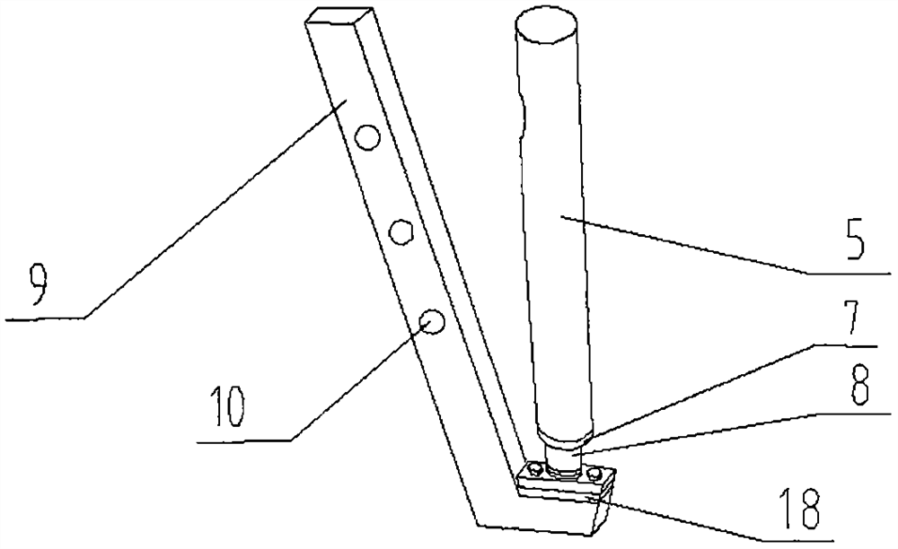
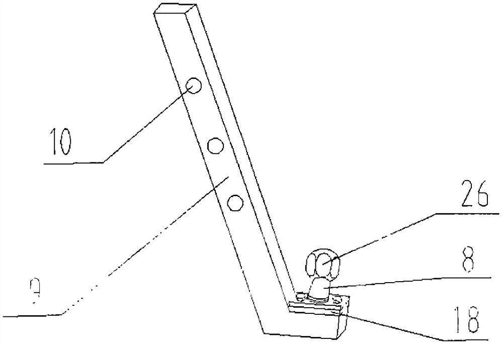
[0069] figure 1 It is the present embodiment: a structural schematic diagram of a combination resistance bar of a tiller. At the same time, combined with figure 2 , image 3 , Figure 4 , Figure 5 , specify. The internal structure, transmission mode, and operation method of the micro-tiller are all prior art, and will not be repeated.
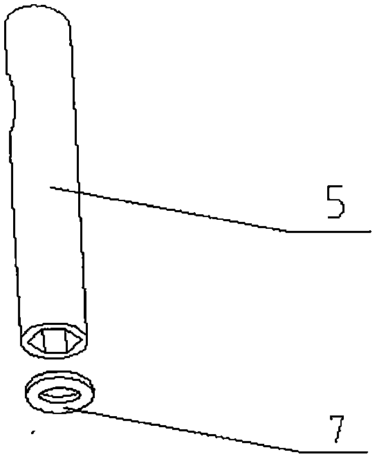
[0070] This embodiment is a tiller with double resistance bars and a hexahedron connecting device. The tiller comprises: a hexahedron coupling device, a front part and a rear part. The hexahedron coupling device divides the tiller into a front part and a rear part. The hexahedral connection device includes: a hexahedral ball 26, a flat cap 7, the lower end surface of the auxiliary resistance rod 5, the side wall of the inner hexagonal tube, the corners of the hexahedral ball 26, the corners of the inner hexagonal tube, and the connecting cylinder 8. The front portion includes: a frame 12, an engine 13, a gearbox 11, a walking box, an ...
Embodiment 2
[0082] Figure 6 It is the present embodiment: a structural schematic diagram of a combination resistance bar of a tiller. Simultaneously combined with Figure 7 , Figure 8 , Figure 9 , Figure 10 , specify. The internal structure, transmission mode, and operation method of the tiller are prior art and will not be repeated.
[0083] This embodiment is a tiller with double resistance rods and through-hole ball connection device. It includes: a through-hole ball connection device, a front part and a rear part. The through-hole ball coupling device divides the tiller into a front part and a rear part. The through-hole ball connection device includes: a through-hole ball 25, a top wire cap 6, a direct pin 24, the lower end surface of the auxiliary resistance rod 5, a round pipe, a connecting cylinder 8, an upper round leather pad 28, a lower round leather pad, Circlip 22, jackscrew, jackscrew hole 23. The middle part of the upper leather pad 28 and the lower leather pad...
Embodiment 3
[0095] Figure 11 It is the present embodiment: a structural schematic diagram of a combination resistance bar of a tiller. Simultaneously combined with Figure 12 , Figure 13 , Figure 14 , Figure 15 , specify. The internal structure, transmission mode, and operation method of the tiller are prior art and will not be repeated.
[0096] This embodiment is a tiller with double resistance bars and a hexahedron connecting device. The tiller comprises: a hexahedron connecting device, a front part and a rear part. The hexahedron coupling device divides the tiller into a front part and a rear part. The hexahedral connection device includes: a hexahedral ball 26, a threaded cap 27, the lower end surface of the auxiliary resistance rod 5, the side wall of the inner hexagonal tube, the corners of the hexahedral ball 26, the corners of the inner hexagonal tube, and the connecting cylinder 8. The front portion includes: a frame 12, a block, an engine 13, a gearbox 11, a walking...
PUM
 Abstract
Description
Claims
Application Information
 - R&D Engineer
- R&D Manager
- IP Professional
- Industry Leading Data Capabilities
- Powerful AI technology
- Patent DNA Extraction
Browse by: Latest US Patents, China's latest patents, Technical Efficacy Thesaurus, Application Domain, Technology Topic, Popular Technical Reports.
© 2024 PatSnap. All rights reserved.Legal|Privacy policy|Modern Slavery Act Transparency Statement|Sitemap|About US| Contact US: help@patsnap.com


