
Sound production adjusting device of magnetic type buzzer for instrument equipment and adjusting method thereof

An adjustment device, magnetic suction technology, applied in the direction of instruments, sounding equipment, etc., can solve the problems of easy sound movement, inconvenient connection with the main body of the buzzer, and the volume of the sound adjustment device cannot meet the actual needs, so as to avoid misalignment Effect

Pending Publication Date: 2021-12-03
江苏鑫长隆机电有限公司
View PDF0 Cites 0 Cited by
  • Summary
  • Abstract
  • Description
  • Claims
  • Application Information

AI Technical Summary

Problems solved by technology

[0004] The purpose of the present invention is to provide a sounding adjustment device for a magnetic buzzer used in instrumentation equipment and an adjustment method thereof, to solve the problem of the sounding adjustment device for a magnetic buzzer currently on the market proposed by the above-mentioned background technology. It is inconvenient to connect with the main body of the buzzer during use. At the same time, the existing sound adjustment device is easy to move after the adjustment is completed, so that the volume adjusted by the sound adjustment device cannot meet the actual needs.

Method used


Image

  • Sound production adjusting device of magnetic type buzzer for instrument equipment and adjusting method thereof
  • Sound production adjusting device of magnetic type buzzer for instrument equipment and adjusting method thereof
  • Sound production adjusting device of magnetic type buzzer for instrument equipment and adjusting method thereof

Examples


Embodiment Construction

[0021] The following will clearly and completely describe the technical solutions in the embodiments of the present invention with reference to the accompanying drawings in the embodiments of the present invention. Obviously, the described embodiments are only some, not all, embodiments of the present invention. Based on the embodiments of the present invention, all other embodiments obtained by persons of ordinary skill in the art without making creative efforts belong to the protection scope of the present invention.

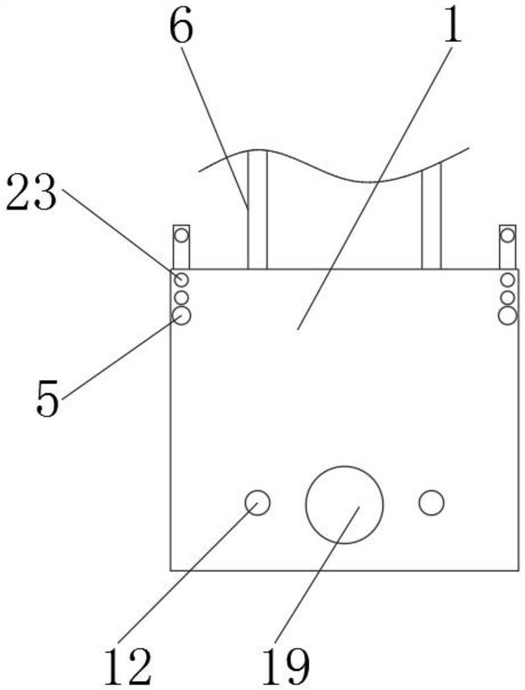
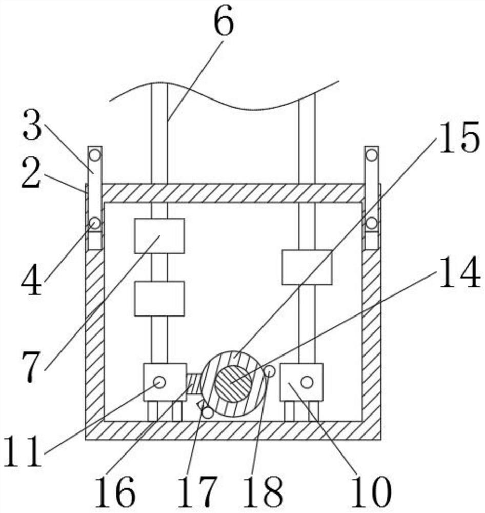
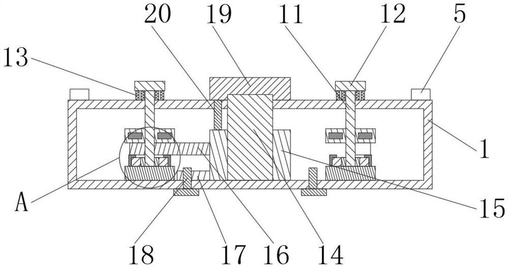
[0022] see Figure 1-5 , the present invention provides a technical solution: a sounding adjustment device for a magnetic buzzer for instrumentation equipment, including a device housing 1, a mounting groove 2, a connecting plate 3, a limit hole 4, a fastening bolt 5, a connecting wire 6. Resistor 7, fixed base 8, conductive sheet 9, fixed bracket 10, first limit rod 11, rubber pad 12, telescopic spring 13, fixed shaft 14, rotating ring 15, energized sheet 16,...


PUM


Abstract

The invention discloses a sound production adjusting device of a magnetic type buzzer for instrument equipment and an adjusting method thereof. The sound production adjusting device comprises a device shell, a through hole and a connecting hole; and the upper surface of an electrifying sheet is provided with the through hole, and the upper surface of the device shell is provided with the connecting hole. The sound production adjusting device of the magnetic type buzzer for the instrument equipment is provided with connecting wires, the number of resistors on the connecting wires is different, and a rotating ring is connected with the electrifying piece; the rotating ring is rotated to enable the electrifying piece to be connected with different connecting wires, and therefore the purpose of adjusting the volume is achieved; a second limiting rod is arranged at the bottom of the device shell; a positioning block is arranged on the outer side face of the rotating ring, so that the electrifying piece can accurately move to the connecting position; a first limiting rod is arranged, and the first limiting rod can ascend and descend through a telescopic spring, so that circuit connection can be completed, the position of the rotating ring can be limited, and dislocation of the rotating ring is avoided; and the connecting plate is arranged, and the length of the connecting plate can be adjusted, so that the mounting distance of the device can be adjusted.

Description

technical field [0001] The invention relates to the technical field of a sounding adjustment device for a magnetic buzzer, in particular to a sounding adjustment device for a magnetic buzzer for instrument equipment and an adjusting method thereof. Background technique [0002] The buzzer is an electronic sounder with an integrated structure. It is powered by DC voltage and is widely used as a sounding device in electronic products such as computers, printers, copiers, alarms, electronic toys, automotive electronic equipment, telephones, and timers. . Buzzers are mainly divided into two types: piezoelectric buzzers and electromagnetic buzzers. The buzzer is represented by the letter "H" or "HA" in the circuit (the old standard uses "FM", "ZZG", "LB", "JD", etc.). The piezoelectric buzzer is mainly composed of a multivibrator, a piezoelectric buzzer, an impedance matcher, a resonance box, and a casing. Some piezoelectric buzzer housings are also equipped with light-emittin...

Claims


Application Information

Patent Timeline
IPC IPC(8): G10K9/13G10K9/20G10K9/22
CPCG10K9/13G10K9/20G10K9/22
Inventor 钱苏文钱江萍李欢
Owner 江苏鑫长隆机电有限公司
Learn More