
Filter device

A filter device and waveguide technology, which is applied in the directions of waveguides, waveguide-type devices, circuits, etc., can solve the problems of complicated design process of the filter device and so on.

Inactive Publication Date: 2021-11-30
THE FUJIKURA CABLE WORKS LTD
View PDF5 Cites 0 Cited by
  • Summary
  • Abstract
  • Description
  • Claims
  • Application Information

AI Technical Summary

Problems solved by technology

Like this, the design process of the filtering device is required to make the interdependent resonator R 1 ~R 5 The optimization of the area and the size of each coupling window becomes complicated

Method used


Image

  • Filter device
  • Filter device
  • Filter device

Examples


no. 1 approach 〕

[0020] (Structure of filter device)

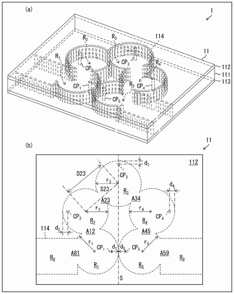
[0021] refer to figure 1 The structure of the filter device 1 according to the first embodiment of the present invention will be described. figure 1 (a) is a perspective view of the filter device 1 . figure 1 (b) is a plan view of the columnar waveguide 11 included in the filter device 1 .

[0022] The filter device 1 includes a plurality of (n, n is an arbitrary integer greater than or equal to 2) resonators R as electromagnetic coupling 1 ~R n Functional pillar wall waveguide 11 . In this embodiment, the case of n=5 will be described. That is, the cylindrical wall waveguide 11 serves as five resonators R 1 ~R 5 function. Resonator R 2 is the resonator R stated in the claims (n-1) / 2 As an example, the resonator R 3 is the resonator R stated in the claims (n+1) / 2 As an example, the resonator R 4 is the resonator R stated in the claims (n+1) / 2+1 As an example, the resonator R 5 is the resonator R stated in the claims (n+1) / 2...


PUM


Abstract

The purpose of the present invention is to make it easy to design a filter device having a desired characteristic. This filter device is provided with a post wall waveguide that functions as a resonator group including combined five resonators (R1-R5). Inside the respective resonators (R1, R2), control posts (CP1, CP2) are provided, and the shortest distance (di) from a control post (CPi) to a narrow wall of a resonator (Ri) satisfies d1>d2. Inside the respective resonators (R4, R5), control posts (CP4, CP5) are provided, and the shortest distance (dj) from a control post (CPj) to a narrow wall of a resonator (Rj) satisfies d4<d5.

Description

technical field [0001] The present invention relates to filter devices of the resonator coupling type. Background technique [0002] A bandpass filter device assumed to be used in the microwave frequency band and the millimeter wave frequency band is described in, for example, Patent Document 1 or the like. A bandpass filter is one form of a filter. [0003] These filtering devices are realized by using the technology of Post-Wall Waveguide (PWW, Post-Wall Waveguide). Specifically, these filter devices are manufactured using a dielectric substrate sandwiched between a pair of conductor layers. A plurality of resonators coupled to each other are formed inside the substrate. In these multiple resonators, a pair of conductor layers is used as a pair of wide walls, and a column wall composed of a plurality of conductor columns arranged in a grid shape is used as a narrow wall. [0004] A coupling window is provided in a part of the column wall separating two adjacent resonat...

Claims


Application Information

Patent Timeline
IPC IPC(8): H01P1/208H01P3/12
CPCH01P1/2088H01P1/2002H01P3/121
Inventor 上道雄介
Owner THE FUJIKURA CABLE WORKS LTD
Learn More