
Emergency protection circuit device with autonomous safety alarm function and use method thereof

A safety alarm and protection circuit technology, applied in emergency protection devices, circuits, protection switches, etc., can solve problems such as circuit short circuit, electrical equipment circuit short circuit, and circuit failure, and achieve the effect of improving precision and accuracy

Inactive Publication Date: 2021-11-30
汪春燕
View PDF0 Cites 1 Cited by
  • Summary
  • Abstract
  • Description
  • Claims
  • Application Information

AI Technical Summary

Problems solved by technology

[0004] The purpose of the present invention is to solve: in the process of using the emergency protection circuit, most of the devices of the emergency protection circuit are relatively large, and when the electrical equipment is overloaded or the circuit is short-circuited, the overload protection in the emergency protection circuit device will often directly give The circuit forms a short circuit, so that when the circuit solves the problem of electrical equipment overload or circuit short circuit, it is easy to cause the problem that the circuit still cannot be used normally

Method used


Image

  • Emergency protection circuit device with autonomous safety alarm function and use method thereof
  • Emergency protection circuit device with autonomous safety alarm function and use method thereof
  • Emergency protection circuit device with autonomous safety alarm function and use method thereof

Examples


Embodiment 1

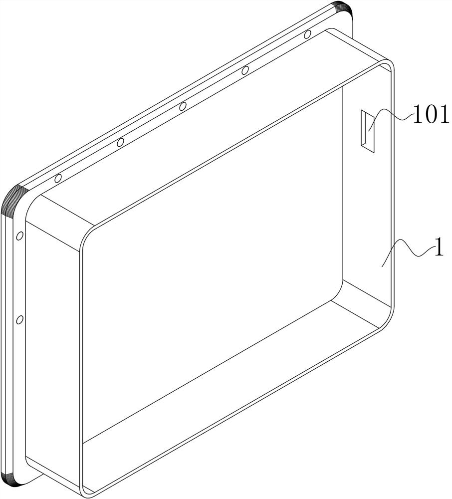
[0063] Such as figure 1 As shown, this embodiment proposes an emergency protection circuit device with an autonomous safety alarm function, including an access housing 1, which shields the internal and external circuits of the device from each other, and the inner bottom of the access housing 1 is provided with a circuit access mechanism 2. Connect the external circuit to the inside of the device for detection. The inside of the access shell 1 is provided with a circuit monitoring mechanism 3 on the top of the circuit access mechanism 2, and the inside of the access shell 1 is provided with a circuit breaker on the side of the circuit monitoring mechanism 3. Reset mechanism 4, current circuit devices mostly use an ammeter to monitor the current value, and then use an electromagnetic switch to control the opening and closing of the circuit. For users, the two need to be carried out separately, so it is necessary to use the circuit breaker reset mechanism 4 to control the circuit...

Embodiment 2

[0065] The scheme in embodiment 1 is further introduced below in conjunction with specific working methods, see the following description for details:

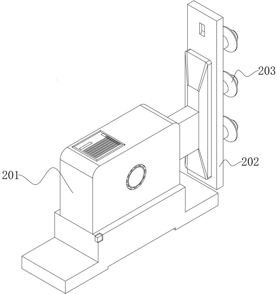
[0066] Such as figure 1 , figure 2 and image 3 As shown, as a preferred embodiment, on the basis of the above method, further, the circuit access mechanism 2 includes two connectors 201, and one side of the connectors 201 is fixed with an assembly line board 202, and the circuit passes through the assembly line board 202 can be connected with the connector 201, so as to realize the internal circuit communication. One side of the assembly line board 202 is fixedly connected with three terminal posts 203 connected through the access shell 1, and an inner shield is embedded in the access shell 1. Connect the terminal 203 to the external circuit. At this time, the entire device can be connected to the circuit, and the inner shielding network can shield the magnetic field generated by the internal circuit to avoid mutual influe...

Embodiment 3

[0068] The schemes in Embodiment 1 and Embodiment 2 are further introduced below in conjunction with specific working methods, see the following description for details:

[0069] Such as figure 1 and Figure 4 As shown, as a preferred embodiment, on the basis of the above method, further, the circuit monitoring mechanism 3 includes a circuit detection box 301, and the bottom end of the circuit detection box 301 is fixedly provided with a first line fixedly connected to the side of the connector 201. Tube 302, when the circuit is connected to the circuit detection box 301 through the first wire tube 302, the circuit detection meter in the circuit detection box 301 can detect the current value in the circuit in real time, and one side of the circuit detection box 301 is embedded with a circuit display The screen 303 is displayed on the circuit display screen 303, which is convenient to clarify the specific situation of the circuit in time. The circuit inspection box 301 is fixe...


PUM


Abstract

The invention provides an emergency protection circuit device with an autonomous safety alarm function and a use method thereof, which belong to the field of emergency protection circuit devices. The emergency protection circuit device comprises an access shell, a circuit access mechanism is arranged at the bottom end of the interior of the access shell, and a circuit monitoring mechanism located at the top of the circuit access mechanism is arranged on the inner side of the access shell; the access shell is internally provided with an open circuit reset mechanism located on one side of the circuit monitoring mechanism, the access shell is internally provided with a circuit protection replacement mechanism located on one side of the open circuit reset mechanism, the access shell is internally provided with a buffer mechanism located between the circuit access mechanism and the circuit monitoring mechanism, and the top end of the access shell is provided with an alarm mechanism. The circuit can be controlled through the arranged open circuit reset mechanism, and the short circuit reset control device can make a corresponding response to an overlarge current condition according to a current value condition of the circuit, and reset is completed after the circuit is repaired.

Description

technical field [0001] The invention belongs to the field of emergency protection circuit devices, and relates to an emergency protection circuit device, in particular to an emergency protection circuit device with an autonomous safety alarm function and a use method thereof. Background technique [0002] The protection circuit refers to a circuit designed to prevent such unstable factors from affecting the circuit effect in view of some unstable factors in the power circuit. For example, there are over-current protection, over-voltage protection, over-heat protection, no-load protection, short-circuit protection, etc. During the use of the circuit, when the electrical equipment is overloaded or the circuit is short-circuited, danger is often prone to occur, so it is particularly important to design an emergency protection circuit. [0003] In the process of using the emergency protection circuit, most of the emergency protection circuit devices are relatively large, and wh...

Claims


Application Information

Patent Timeline
Patent Type & Authority Applications(China)
IPC IPC(8): H01H71/24H01H71/02H01H71/04H01H71/08H01H71/12
CPCH01H71/24H01H71/2463H01H71/08H01H71/04H01H71/12H01H71/02
Inventor 汪春燕
Owner 汪春燕
Learn More