Ultrasonic radar detection equipment

A radar detection and ultrasonic technology, applied in the direction of radio wave measurement systems, instruments, etc., can solve the problems of cumbersome manual operations, error-prone, slow adjustment time, etc., and achieve the effect of ultrasonic radar performance reaching the standard

Pending Publication Date: 2021-11-26
上海网车科技有限公司
View PDF0 Cites 1 Cited by
  • Summary
  • Abstract
  • Description
  • Claims
  • Application Information

AI Technical Summary

Problems solved by technology

[0006] The purpose of the present invention is to provide an ultrasonic radar detection device to solve the problems that the current ultrasonic radar detection proposed in the above background technology mostly adopts manual operation, which is low in efficiency, error-prone, cumbersome manual operation, and slow adjustment time.

Method used


Image

  • Ultrasonic radar detection equipment
  • Ultrasonic radar detection equipment
  • Ultrasonic radar detection equipment

Examples


Embodiment Construction

[0029] The following will clearly and completely describe the technical solutions in the embodiments of the present invention with reference to the accompanying drawings in the embodiments of the present invention. Obviously, the described embodiments are only some, not all, embodiments of the present invention. Based on the embodiments of the present invention, all other embodiments obtained by persons of ordinary skill in the art without making creative efforts belong to the protection scope of the present invention.

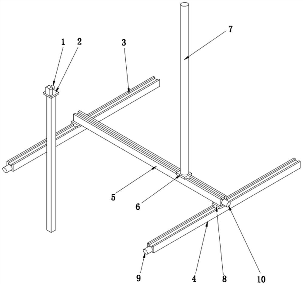
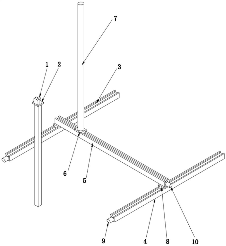
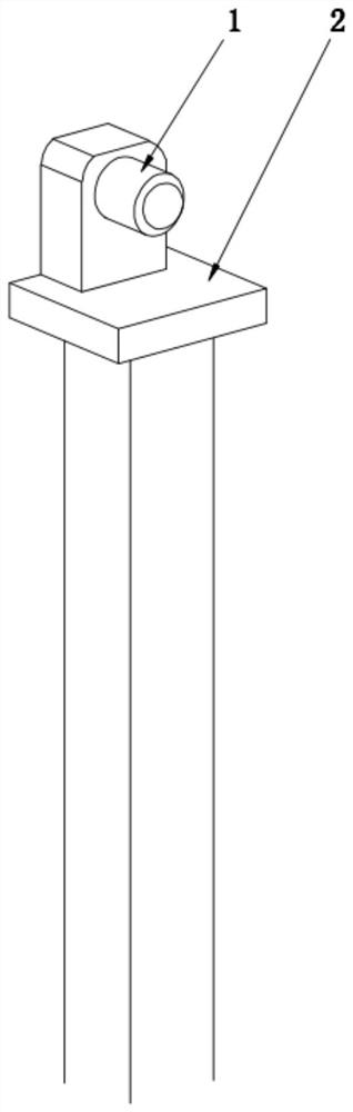
[0030] see Figure 1-Figure 6 , an embodiment provided by the present invention: an ultrasonic radar detection device, which includes an ultrasonic radar 1, a test station 2, an X-axis guide rail 1 3, an X-axis guide rail 2 4, a Y-axis guide rail 5, a slider 2 6, Target 7, slider one 8, X-axis motor 9, Y-axis motor 10, controller 11 and host computer 12, wherein the ultrasonic radar 1 is plugged into the upper end of the test station 2, and the plug interface ...


PUM


Abstract

The invention discloses ultrasonic radar detection equipment. An ultrasonic radar is inserted into the upper end of a test station, a first X-axis guide rail and a second X-axis guide rail are symmetrically arranged on the two sides of the test station, a first sliding block driver is installed at one end of each of the first X-axis guide rail and the second X-axis guide rail, and a Y-axis guide rail is arranged on the upper portion of each of the first X-axis guide rail and the second X-axis guide rail; first sliding blocks are arranged below the two ends of the Y-axis guide rail, the Y-axis guide rail is slidably matched with the upper portion of the first X-axis guide rail and the upper portion of the second X-axis guide rail through the first sliding blocks, and the power output end of a first sliding block driver is matched with the first sliding blocks; and a second sliding block is slidably arranged at the upper end of the Y-axis guide rail, the second sliding block is connected with the power output end of a second sliding block driver at the end of the Y-axis guide rail, a target object is fixedly installed at the upper end of the second sliding block, and the first sliding block driver, the second sliding block driver and the ultrasonic radar are all electrically connected with the controller. According to the invention, manual operation is not needed, the detection efficiency and accuracy are improved, the operation is simple and convenient, and the adjustment time is short.

Description

technical field [0001] The invention relates to the technical field of automotive electronics, in particular to ultrasonic radar, and in particular to an ultrasonic radar detection device. Background technique [0002] Ultrasonic radar is an extremely common sensor. If you feel that the ultrasonic radar is a little strange, then it has a more popular name - reversing radar. It is a safety auxiliary device when the car is parked or reversed. It can inform the driver of the surrounding obstacles by sound or a more intuitive display. , and help the driver eliminate the defects of blind spots and blurred vision. The working principle of the ultrasonic radar is to measure the distance by the time difference between sending out ultrasonic waves through the ultrasonic transmitting device and receiving the sent ultrasonic waves through the receiver. [0003] Ultrasonic radar is used for distance detection of obstacles around the vehicle. The quality inspection of ultrasonic rada...

Claims


Application Information

Patent Timeline
Patent Type & Authority Applications(China)
IPC IPC(8): G01S7/52
CPCG01S7/52004
Inventor 丰彬胡益波
Owner 上海网车科技有限公司
Why Eureka
Try Eureka