Practical deduster equipment

A technology for dust collectors and equipment, which is applied to the parts of connecting devices, devices that prevent contact with live contacts, electrical components, etc. Open and other problems to achieve the effect of increasing safety performance and reducing accidental electric shock accidents

Inactive Publication Date: 2018-06-29
广州天亿科技有限公司
View PDF5 Cites 0 Cited by
  • Summary
  • Abstract
  • Description
  • Claims
  • Application Information

AI Technical Summary

Problems solved by technology

[0002] The dust collector needs to be moved around when in use. Since the plug and the socket of the existing dust collector are generally connected by friction fit, no other locking device is provided, so when the dust collector is moved when the staff touches it, it is easy to break it. The plug of the dust collector is knocked open, which affects the use of the dust collector, and the existing sockets connected to the dust collector are directly charged, so electric shock accidents are likely to occur when plugging and unplugging the plug

Method used


Image

  • Practical deduster equipment
  • Practical deduster equipment
  • Practical deduster equipment

Examples


Embodiment Construction

[0022] The preferred embodiments of the present invention will be described in detail below in conjunction with the accompanying drawings, so that the advantages and features of the present invention can be more easily understood by those skilled in the art, so as to define the protection scope of the present invention more clearly.

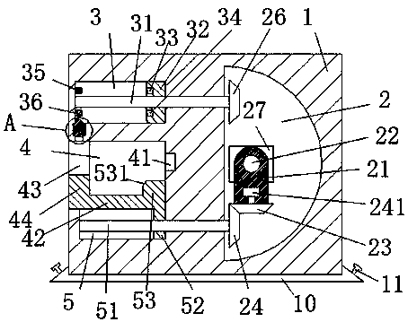
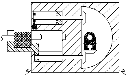
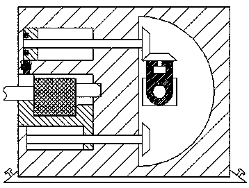
[0023] refer to Figure 1-6 A practical dust collector device shown includes a power transmission seat 1, a suction cup 10 is fixedly installed on the bottom of the power transmission seat 1, and a lifting ring 11 is installed on the left and right sides of the suction cup 10, and the lifting ring 11 is used for To pick up the suction cup 10, the suction cup is used to increase the stability of the power transmission base 1, the left end of the power transmission base 1 is provided with a socket 4, and the right end of the socket 4 is provided with a power transmission port 41, the The bottom end of the socket 4 is provided with a first sliding c...


PUM


Abstract

The invention discloses practical deduster equipment comprising a power transmission base. The bottom part of the power transmission base is fixedly provided with a sucking disc. The left and right sides of the sucking disc are respectively provided with a lifting ring. The left end surface of the power transmission base is provided with a jack. The right end part of the jack is provided with a power transmission port. The bottom end part of the jack is provided with a first slide cavity which is communicated with the jack. The power transmission base is provided with a second slide cavity above the jack. The power transmission base is provided with a turning slot on the right end of the jack. The turning slot is provided with an operation device. A slide frame is smoothly arranged in thejack in a left-and-right direction. The structure is simple, the production cost is low and power supply is safe and stable so that the accident of electric shock can be effectively eliminated, automatic connection and disconnection of the power connection head and the power transmission port can be realized, the situation that the power connection head of the plug of the deduster is separated from the power transmission port because of mistakenly hitting and colliding the electric wire can be avoided, and the use requirements of the deduster can be met.

Description

technical field [0001] The invention relates to the field of dust collectors, in particular to a practical dust collector equipment. Background technique [0002] The dust collector needs to be moved around when in use. Since the plug and the socket of the existing dust collector are generally connected by friction fit, no other locking device is provided, so when the dust collector is moved when the staff touches it, it is easy to break it. The plug of the dust collector breaks open, which affects the use of the dust collector, and the existing sockets connected to the dust collector are all directly charged, so electric shock accidents are likely to occur when plugging and unplugging the plug. Contents of the invention [0003] The technical problem to be solved by the present invention is to provide a practical dust collector device, which can solve the above-mentioned problems in the prior art. [0004] In order to solve the above problems, the present invention adopt...

Claims


Application Information

Patent Timeline
Patent Type & Authority Applications(China)
IPC IPC(8): H01R13/639H01R13/70H01R13/629H01R13/44
CPCH01R13/639H01R13/44H01R13/629H01R13/701
Inventor 沈科丹
Owner 广州天亿科技有限公司
Why Eureka
Try Eureka