Intelligent electrical equipment controller

A technology of intelligent electrical equipment and controllers, which is applied to the construction parts of electrical equipment, electrical components, chemical instruments and methods, etc., which can solve the problems of fewer inspections by personnel, more dust, and difficult heat dissipation of the controller body, so as to reduce access The effect of the probability of cooling inside the enclosure

Active Publication Date: 2021-11-23
NINGBO XINGHONG INTELLIGENT TECH CO LTD
View PDF12 Cites 0 Cited by
  • Summary
  • Abstract
  • Description
  • Claims
  • Application Information

AI Technical Summary

Problems solved by technology

[0003] Electrical equipment is widely used in life and work. Some of the equipment controllers on the market are generally intelligent control equipment operation. The parameters of manual control equipment operation are used in conjunction with each other. At present, some electrical controllers are installed in the factory Next to the equipment, it is convenient for personnel to control the equipment. Since the equipment in the factory is automatically operated, it can be operated for a long time only by inputting parameters when going to work, and personnel do not need to stay beside the controller for a long time. Continuous work, coupled with the fact that there is a lot of dust inside the factory, is easy to enter the controller housing, which leads to the problem of difficult heat dissipation of the controller body. The existing controllers are usually equipped with cooling fans at the processor and other components to dissipate heat. However, The fan itself will generate a certain amount of heat. At the same time, with the rotation of the fan, it will also generate a certain amount of suction while exhausting the gas, which will suck the dust from the outside into the controller casing, affecting the normal use of other internal control components. The number of times is less, which leads to the shutdown of the production line after problems occur. For this reason, we propose an intelligent electrical equipment controller

Method used


Image

  • Intelligent electrical equipment controller
  • Intelligent electrical equipment controller
  • Intelligent electrical equipment controller

Examples


Embodiment Construction

[0027] The following will clearly and completely describe the technical solutions in the embodiments of the present invention with reference to the accompanying drawings in the embodiments of the present invention. Obviously, the described embodiments are only some, not all, embodiments of the present invention. Based on the embodiments of the present invention, all other embodiments obtained by persons of ordinary skill in the art without making creative efforts belong to the protection scope of the present invention.

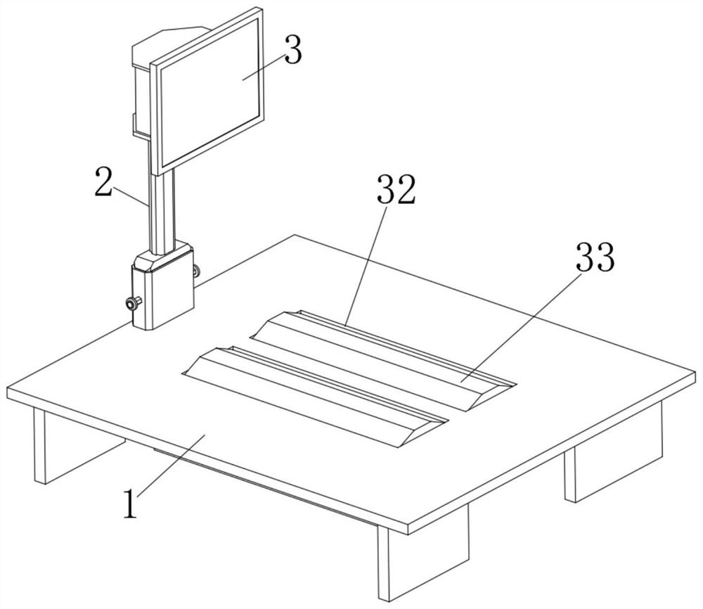
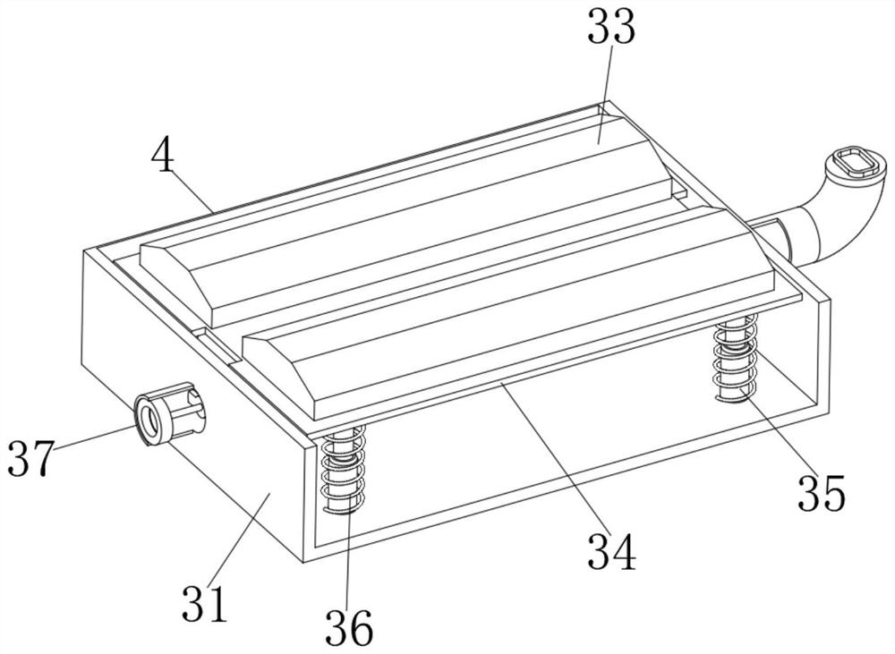
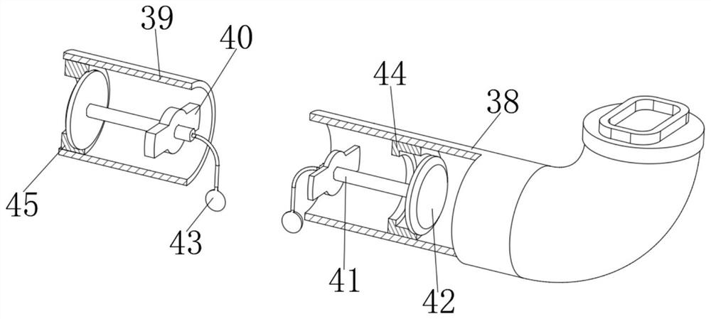
[0028] see Figure 1-11 , an intelligent electrical equipment controller in the figure, including a floor 1 installed next to the equipment in the factory area, a support assembly 2, a controller 3 for equipment control, and an air blowing assembly 4. The support assembly 2 is installed at one end of the floor 1 , and the controller 3 is fixed on the top of the supporting assembly 2, and the inflating assembly 4 for manually generating gas is installed at the ...


PUM


Abstract

An intelligent electrical equipment controller disclosed by the present invention comprises a floor installed beside plant equipment, a support assembly, a controller for equipment control and an air blowing assembly. The support assembly is installed at one end of the floor, the controller is fixed at the top of the support assembly, and the air blowing assembly for generating gas by labor is installed at the bottom of the floor. Through the mutual cooperation effect of the air blowing assembly and the heat dissipation and dust removal part in the supporting assembly, pedestrians and carts passing by factory equipment can be utilized to tread the air blowing assembly, so that air pressure is generated, the heat dissipation and dust removal part can move to remove dust and eject air to dissipate heat. Through mutual cooperation of the designed gas collection assembly and the limiting piece, gas can be slowly inflated and rapidly sprayed out, and compared with existing fan rotation heat dissipation, the probability that external gas enters the heat dissipation shell can be greatly reduced.

Description

technical field [0001] The invention relates to the technical field of controllers, in particular to an intelligent electrical equipment controller. Background technique [0002] Electrical equipment (Electrical Equipment) is a general term for generators, transformers, power lines, circuit breakers and other equipment in the power system. Electrical equipment includes primary equipment and secondary equipment. Primary equipment is mainly equipment that directly generates, transmits, and consumes electric energy such as power generation, transformation, transmission, distribution, and consumption, such as generators, transformers, overhead lines, power distribution cabinets, switch cabinets, and so on. Secondary equipment is the equipment that plays the role of control, protection and measurement. Buildings or general workshops such as cables, power distribution cabinets, motors, switch sockets, lamps, air conditioners, electric water heaters, meters, cameras, telephones, c...

Claims


Application Information

Patent Timeline
Patent Type & Authority Applications(China)
IPC IPC(8): H05K7/20B08B1/00B08B5/02
CPCH05K7/20136B08B5/02B08B1/143
Inventor 厉刚
Owner NINGBO XINGHONG INTELLIGENT TECH CO LTD
Why Eureka
Try Eureka