
Steel wire reel and steel wire reel mechanism

A technology for steel wire coils and steel wires, which is applied in the directions of transportation and packaging, transportation of filamentous materials, and processing of thin materials, etc. It can solve the problems of disordered steel wire ropes, difficult to achieve precise winding and unwinding of steel wires, and inability to collect and unwind wires.

Pending Publication Date: 2021-11-23
施帆芳
View PDF0 Cites 0 Cited by
  • Summary
  • Abstract
  • Description
  • Claims
  • Application Information

AI Technical Summary

Problems solved by technology

[0003] However, most of the current electric reels are large in size and lack wire rope reels that can be applied to small mechanical equipment.
In addition, in order to increase the winding volume of the reel, the existing reel often adopts an axial multi-row winding method, and the steel wire rope in the reel is disorderly, it is difficult to realize the precise retraction of the steel wire, and even the situation that the wire cannot be retracted; Or, in order to stabilize the outgoing line, the outgoing line position of the existing reel is mostly led out by a fixed guide device. Taking the reel with axial single-row winding as an example, during the rotation of the reel, the steel wire on the reel The winding position is changing (the winding position is gradually moving away from the guide device or close to the guide device), which makes the take-up and take-up line speed of the steel wire change under the same reel speed, resulting in small and medium-sized precision equipment that requires precise control. reel device

Method used


Image

  • Steel wire reel and steel wire reel mechanism
  • Steel wire reel and steel wire reel mechanism
  • Steel wire reel and steel wire reel mechanism

Examples


Embodiment Construction

[0033] The following will clearly and completely describe the technical solutions in the embodiments of the present invention with reference to the accompanying drawings in the embodiments of the present invention. Obviously, the described embodiments are only part of the embodiments of the present invention, not all of them. Based on the embodiments of the present invention, all other embodiments obtained by persons of ordinary skill in the art without creative efforts fall within the protection scope of the present invention.

[0034] It should be noted that all directional indications (such as up, down, left, right, front, back...) in the embodiments of the present invention are only used to explain the relationship between the components in a certain posture (as shown in the accompanying drawings). Relative positional relationship, movement conditions, etc., if the specific posture changes, the directional indication will also change accordingly.

[0035]In the description...


PUM


Abstract

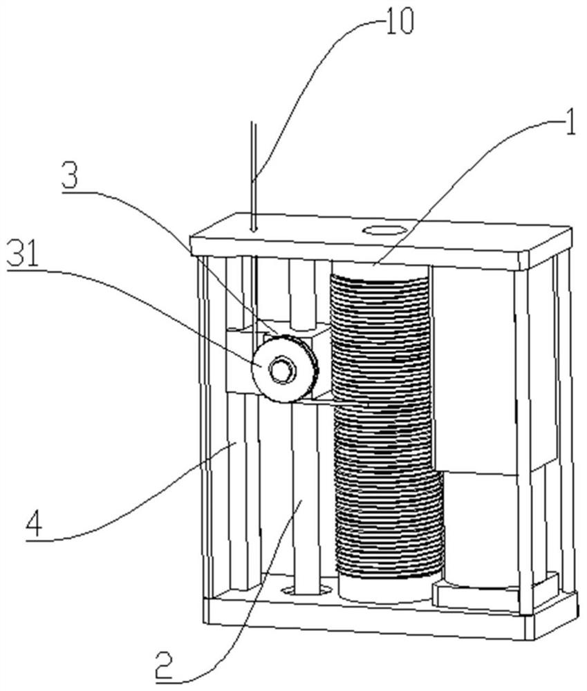
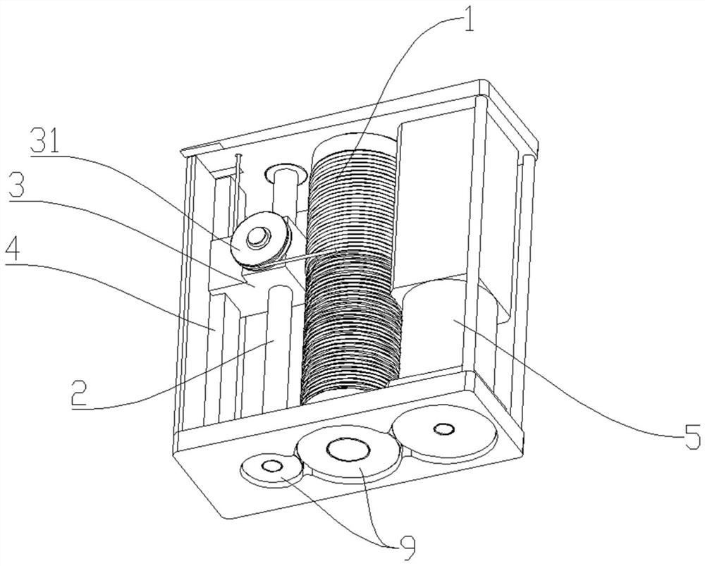
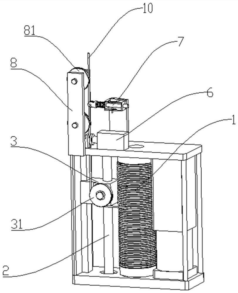
The invention discloses a steel wire reel and a steel wire reel mechanism, the steel wire reel comprises a steel wire winding reel and a steel wire outlet guide mechanism, wherein a steel wire wound on the steel wire winding reel passes through a steel wire guide device of the steel wire guide mechanism and then is discharged, and the guide device can move in the direction parallel to the central axis of the steel wire winding reel. The positive and negative rotation of the steel wire winding reel is used for winding and unwinding the steel wire, and the lifting change of the steel wire guide device can be controlled to be matched with the height change of the wire outlet position on the steel wire winding reel, so that the winding and unwinding are more stable. The steel wire outlet guide mechanism can comprise a lead screw nut pair and a sliding rail, and a nut of the lead screw nut pair serves as a steel wire guide device. The steel wire can be regularly wound and unwound on the steel wire cylinder, and the winding and unwinding linear speed of the steel wire is fixed. The steel wire reel can stably take up and pay off steel wires, accurately control the take-up and pay-off speed and is suitable for occasions needing precise control.

Description

technical field [0001] The invention belongs to the field of reel equipment and specifically designs a steel wire reel and a steel wire reel mechanism capable of realizing the regular retraction and unwinding of steel wires. Background technique [0002] Steel wire reels, also known as wire rope reels, are mainly used to realize the retraction and unwinding of steel wires, and can be divided into two categories: non-electric and electric. Among them, the electric wire rope reel greatly reduces the labor intensity of the operator compared with the non-electric type, and has a more accurate wire rewinding speed, so it is widely used. [0003] However, most of the current electric reels are relatively large in size and lack steel wire rope reels that can be applied to small mechanical equipment. In addition, in order to increase the winding volume of the reel, the existing reel often adopts an axial multi-row winding method, and the steel wire rope in the reel is disorderly, i...

Claims


Application Information

Patent Timeline
IPC IPC(8): B65H75/44B65H59/38B65H63/02B65H63/04B65H57/28
CPCB65H75/4486B65H75/4405B65H75/4439B65H75/4484B65H59/385B65H59/387B65H63/02B65H63/04B65H57/28B65H2701/35
Inventor 施世清
Owner 施帆芳
Learn More